


166
FX3S/FX3G/FX3GC/FX3U/FX3UC Series
Programming Manual - Basic & Applied Instruction Edition
6 What to Understand before Programming
6.1 How to Read Explanation of Instructions
6. What to Understand before Programming
This chapter explains the I/O processing, relationship among instructions and programming method which should be
understood before creating sequence programs.
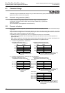
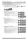
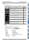
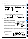
6.1 How to Read Explanation of Instructions
In this manual, applied instructions are explained in the following form.
For the expression methods and basic rules for applied instructions, read in advance "6.5 General rules for applied
instructions" described later.
The above is different from the actual page, as it is provided for explanation only.
265
FX3S/FX3G/FX3GC/FX3U/FX3UC Series
Programming Manual - Basic & Applied Instruction Edition
10 Arithmetic and Logical Operation (
,
,
u
,
y
) – FNC 20 to FNC 29
10.1 FNC 20 – ADD / Addition
1
Introduction
2
Overview
3
Instruction
List
4
Devices
in Detail
5
Specified the
Device &
Constant
6
Before
Programming
7
Basic
Instruction
8
FNC00-FNC09
Program Flow
9
FNC10-FNC19
Move & Compare
10
FNC20-FNC29
Arith. & Logic
Operation
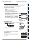
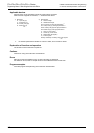
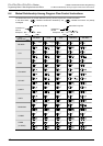
10.1 FNC 20 – ADD / Addition
Outline
This instruction executes addition by two values to obtain the result (A + B = C).
oFor the floating point addition instruction EADD (FNC120), refer to Section 18.8.
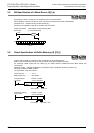
1. Instruction format
2. Set data
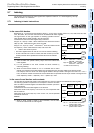
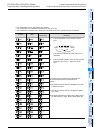
3. Applicable devices
S1: This function is supported only in FX3G/FX3GC/FX3U/FX3UC PLCs.
S2: This function is supported only in FX
3U/FX3UC PLCs.
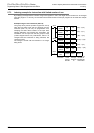
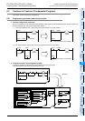
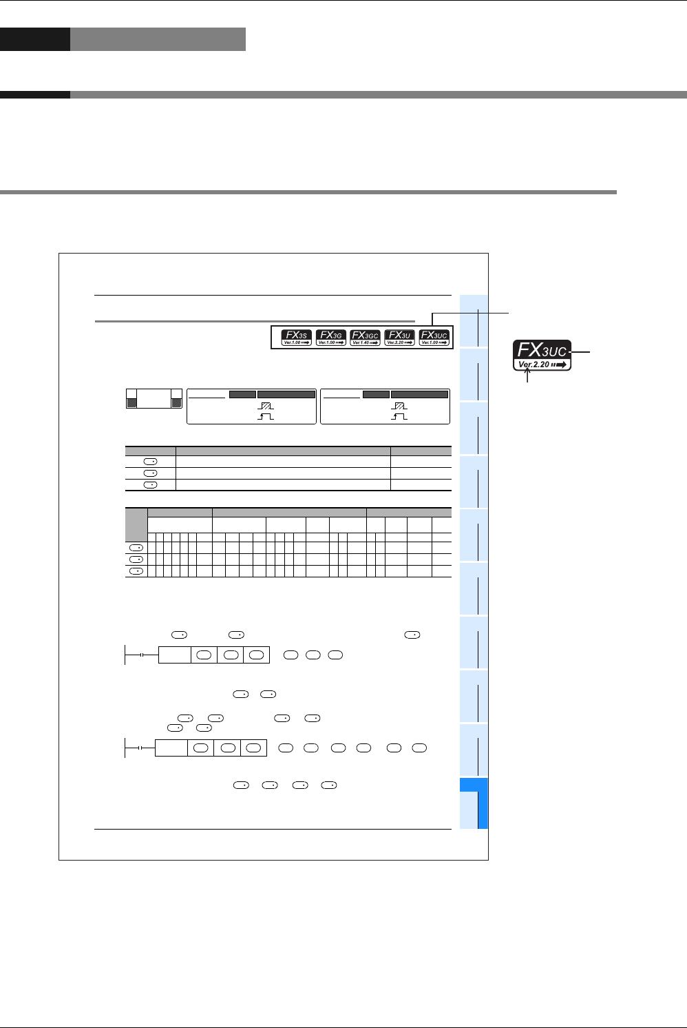
Explanation of function and operation
1. 16-bit operation (ADD and ADDP)
The contents of are added to in binary format, and the addition result is transferred to .
• The most significant bit of each data indicates the sign (positive: 0 or negative: 1), and data is added algebraically.
5 + (8) = 3
• When a constant (K) is specified in or , it is automatically converted into binary format.
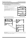
2. 32-bit operation (DADD and DADDP)
The contents of [ +1, ] are added to [ +1, ] in binary format, and the addition result is
transferred to [ +1, ].
• The most significant bit of each data indicates the sign (positive: 0 or negative: 1), and data is added algebraically.
5500 + (8540) = 3040
• When a constant (K) is specified in [ +1, ] or [ +1, ], it is automatically converted into binary
format.
Operand type Description Data type
Data for addition or word device number storing data 16- or 32-bit binary
Data for addition or word device number storing data 16- or 32-bit binary
Word device number storing the addition result 16- or 32-bit binary
Oper-
and
Type
Bit Devices Word Devices Others
System User Digit Specification System User
Special
Unit
Index
Con-
stant
Real
Number
Charac-
ter String
Pointer
XYMTCSD.b KnX KnY KnM KnS T C D R U\G VZModifyKH E ""P
3333333S1 S2 33 3 33
3333333S1 S2 33 3 33
333333S1 S2 33 3
DADD
DADDP
Mnemonic Operation Condition
P
FNC 20
ADD
D
16-bit Instruction
7 steps
ADD
ADDP
Mnemonic Operation Condition
Continuous
Operation
Pulse (Single)
Operation
32-bit Instruction
13 steps
Continuous
Operation
Pulse (Single)
Operation
S
1
S
2
D
S
1
S
2
D
S
2
S
1
D
FNC 20
ADD
S
1
S
2
+
o
Command
input
D
S
1
S
2
D
S
1
S
2
S
2
S
2
S
1
S
1
D
1
D
1
FNC 20
DADD
S
1
S
2
[ +1, ] + [ +1, ]
o>
1, ]
Command
input
D
S
1
S
2
D
S
1
S
2
D
S
1
S
1
S
2
S
2
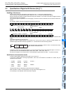
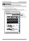
Indicates applicable
PLC versions.
Applicable
series
Expression of applicable versions
– → Ver. 2.20: before Ver. 2.20
– Ver. 2.20 →: Ver. 2.20 or later