117
FX3S/FX3G/FX3GC/FX3U/FX3UC Series
Programming Manual - Basic & Applied Instruction Edition
4 Devices in Detail
4.8 High-Speed Counter [C] (FX3U/FX3UC PLC)
1
Introduction
2
Overview
3
Instruction
List
4
Devices
in Detail
5
Specified the
Device &
Constant
6
Before
Programming
7
Basic
Instruction
8
FNC00-FNC09
Program Flow
9
FNC10-FNC19
Move & Compare
10
FNC20-FNC29
Arith. & Logic
Operation
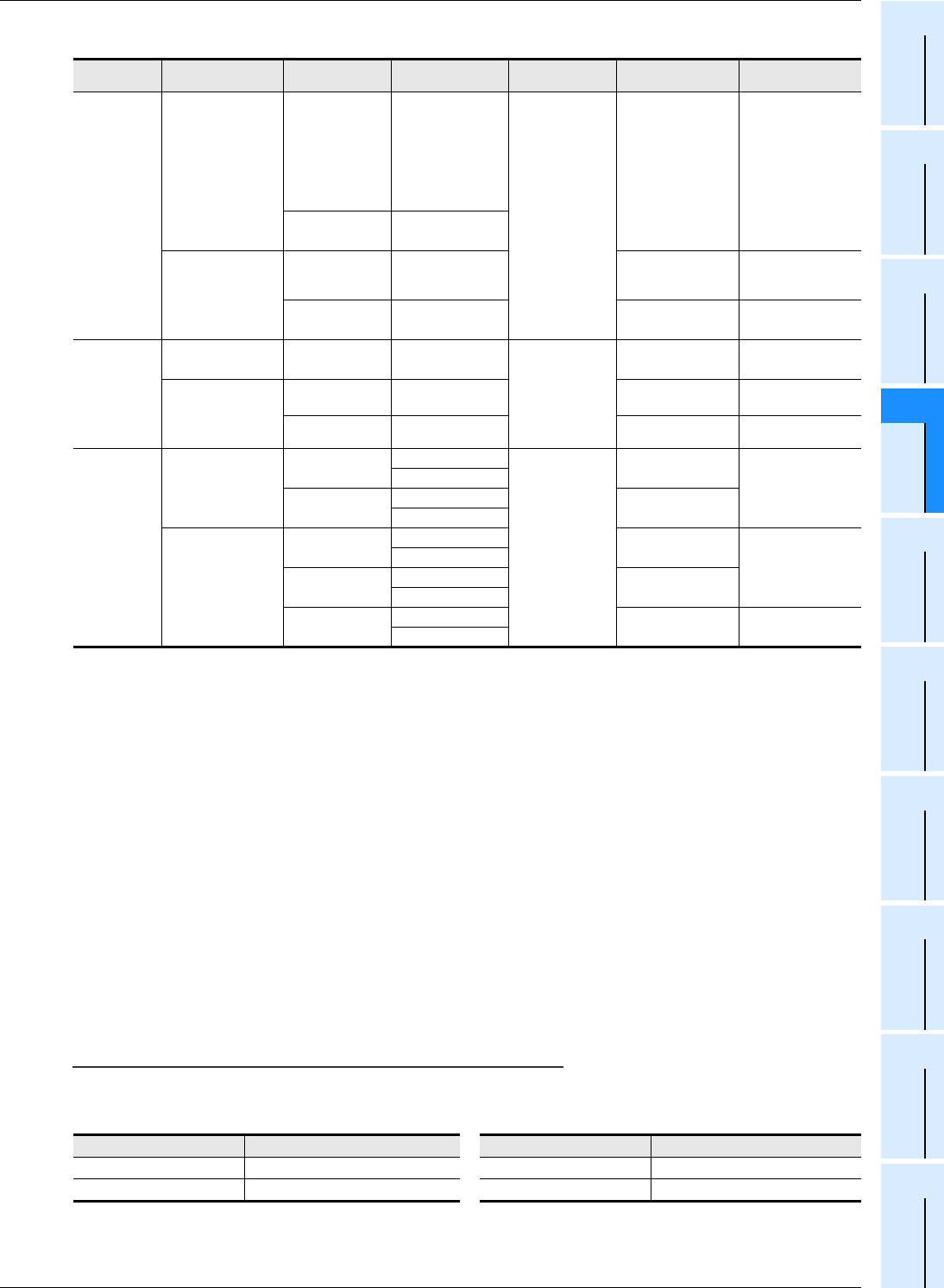
5. High-speed counter device list
*1. They are handled as software counters depending on the operating condition. When they are handled as
software counters, they have limitations on both maximum response frequency and total frequency.
→ For the condition handled as software counters, refer to Subsection 4.8.9.
→ For the total frequency, refer to Subsection 4.8.10.
*2. Cautions on wiring should be considered for these high-speed counters.
→ For the wiring, refer to the Hardware Edition of the main unit.
*3. C244, C245 and C248 are usually used as software counters, but can be used as hardware counters C244
(OP), C245 (OP) and C248 (OP) by combining a special auxiliary relay (M8388, M8390 to M8392).
→ For the method to switch the counter function, refer to Subsection 4.8.7.
*4. 2-phase 2-input counter is usually 1 edge count counter, but can be used as a 4 edge count counter by
combining a special auxiliary relay (M8388, M8198 or M8199).
→ For the method to use a 2-phase 2-input 4 edge count counter, refer to Subsection 4.8.8.
*5. The external reset input is usually reset by turning ON, but can be changed to be reset by turning OFF by
combining special auxiliary relays (M8388 and M8389).
→ For the method to change the logic of the external reset input, refer to Subsection 4.8.6.
*6. The counter C253 is usually used as a hardware counter, but can be used as the counter C253 (OP) not
equipped with reset input by combining special auxiliary relays (M8388 and M8392).
In this case, C253 (OP) is handled as a software counter.
Notation of high-speed counter devices
For some high-speed counters in FX
3U and FX3UC PLCs, the assignment of input terminals will switch when special
auxiliary relays are used.
Such high-speed counter devices are classified below. Note that description as (OP) is not available in programming.
Classification Counter No. Edge count Data length
External reset
input terminal
External start
input terminal
1-phase
1-count input
Hardware counter
*1
C235
*2
C236
*2
C237
*2
C238
*2
C239
*2
C240
*2
−
32-bit
bi-directional
counter
Not provided Not provided
C244(OP)
*3
C245(OP)
*3
−
Software counter
C241
C242
C243
−
Provided
*5
Not provided
C244
*3
C245
*3
−
Provided
*5
Provided
1-phase
2-count input
Hardware counter
*1
C246
*2
C248(OP)
*2*3
−
32-bit
bi-directional
counter
Not provided Not provided
Software counter
C247
C248
*3
−
Provided
*5
Not provided
C249
C250
−
Provided
*5
Provided
2-phase
2-count input
Hardware counter
*1
C251
*2
1
*4
32-bit
bi-directional
counter
Not provided
Not provided
4
*4
C253
*2
1
*4
Provided
*5
4
*4
Software counter
C252
1
*4
Provided
*5
Not provided
4
*4
C253(OP)
*6
1
*4
Not provided
4
*4
C254
C255
1
*4
Provided
*5
Provided
4
*4
Standard Device Numbers Switched Device Numbers Standard Device Numbers Switched Device Numbers
C244 C244(OP) C248 C248(OP)
C245 C245(OP) C253 C253(OP)


