


AOS WPC - Tech Training 69 of 72 Ashland City, TN © 2007
Servicing should only be performed by a Qualified Service Agent
VF BOILER SERVICE MANUAL
TECHNICAL SPECIFICATIONS
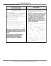
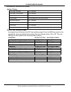
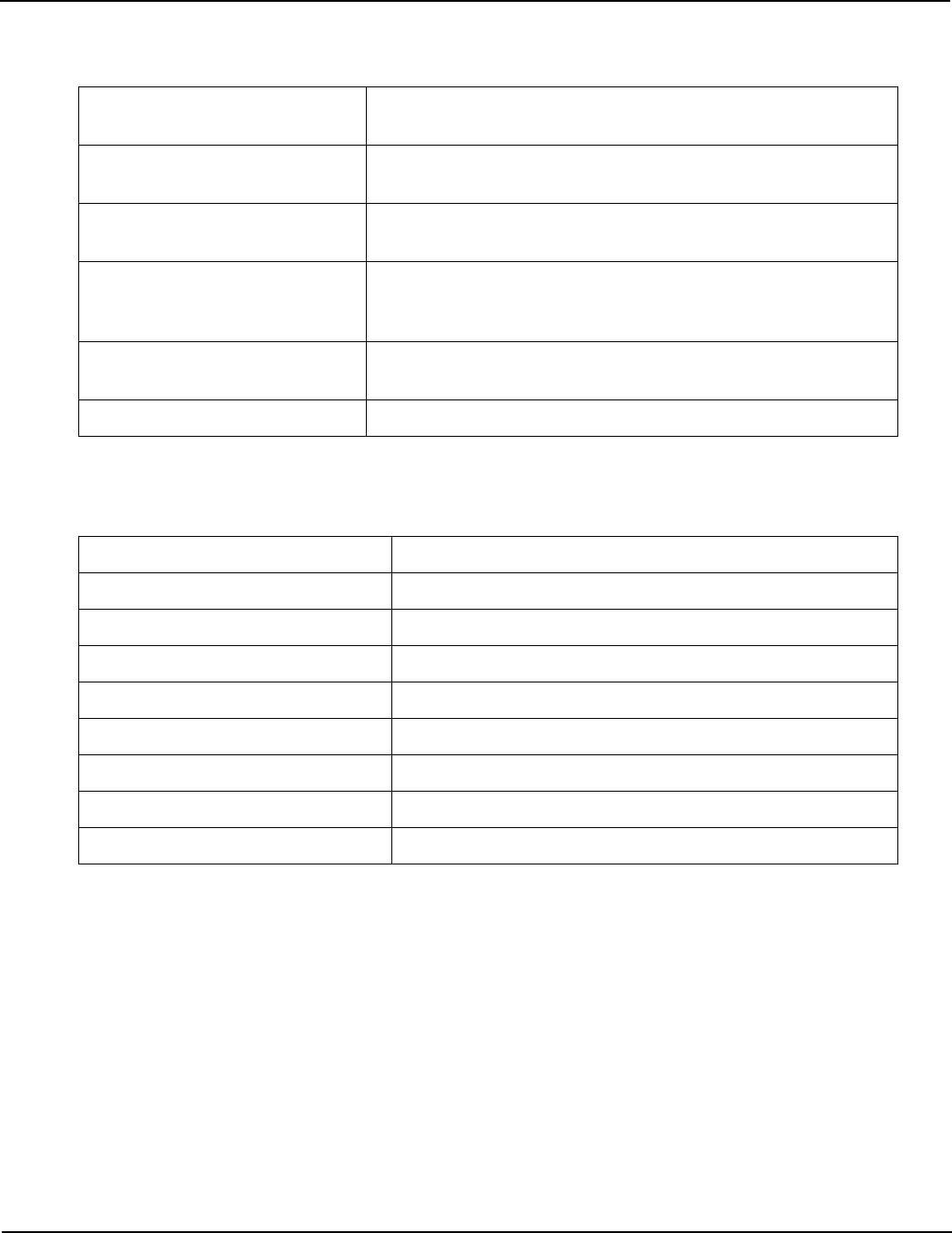
Input Specifications (cont):
†
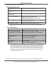
Output Specifications:
†
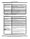
High Blower Prover Pressure
Switch
†. Signal level passed through switches: 24 VAC @ >7ma. (Does not require low-level con-
tacts).
Normally Open, closes on a pressure fall at -4.8" W.C. ± 0.01
†
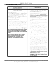
Low Blower Prover Pressure
Switch
Normally Open, closes on a pressure fall at -0.12" W.C.± 0.01
†
Blocked Flue (Exhaust)
Pressure Switch
Normally Closed, opens on a pressure rise at 1.0" W.C. ± 0.1
†
Low Gas Pressure Switch Normally Open, closes on a pressure rise.
Natural Gas Activation Pressure: 4.0" W.C. ± 0.4
Propane Gas Activation Pressure: 6.4 " W.C. ± 0.5
†
Water Flow Switch Normally Open, closes when flow rate exceeds an adjustable
setting (approximately 22 GPM)
†
Low Water Cut Off Switch Normally Closed, opens when water level is low
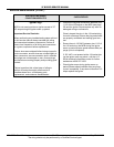
High Speed Combustion Blower 120 VAC, 50/60 Hz, 3A (MCB J15 Socket)
Low Speed Combustion Blower 120 VAC, 50/60 Hz, 3A (MCB J15 Socket)
Hot surface igniter - Silicon Carbide 120 VAC, 50/60 Hz must prove 2.7 AC amp minimum.
Gas Valve 24 VAC, 50/60 Hz, Switched 3.5 A
Low Water Cut Off 24 VAC, 50/60 Hz, Not Switched, 1 A
Alarm 24 VAC, 50/60 Hz, Switched 1 A
Spare 24 VAC, 50/60 Hz, Switched 1 A
IRI Gas Valve N/A on VF boilers.
†
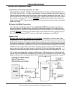
Pump
†.
Field installed boiler circulation pumps (VB models): For outputs up to 120 VAC 5 FLA
use on board remote pump relay connected to TB1 terminal board on the PDB (page 36).
For 120 VAC outputs between 5 and 20 FLA, use an external relay/starter and supply 120
VAC pump power through the 20 amp F2 pump fuse on the PDB (page 37). For outputs
above 120 VAC or 20 FLA use an external relay/starter and a separate dedicated power
supply for the pump, use the on board pump relay Com and N.O. contacts to initiate the
field supplied starter/relay coil only.
120 VAC, 50/60 Hz, maximum 20 FLA
†. Total currents are limited by the input circuit breaker and fuses on the PDB and MCB. See above