


VF BOILER SERVICE MANUAL
AOS WPC - Tech Training 34 of 72 Ashland City, TN © 2007
Servicing should only be performed by a Qualified Service Agent
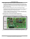
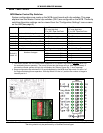
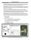
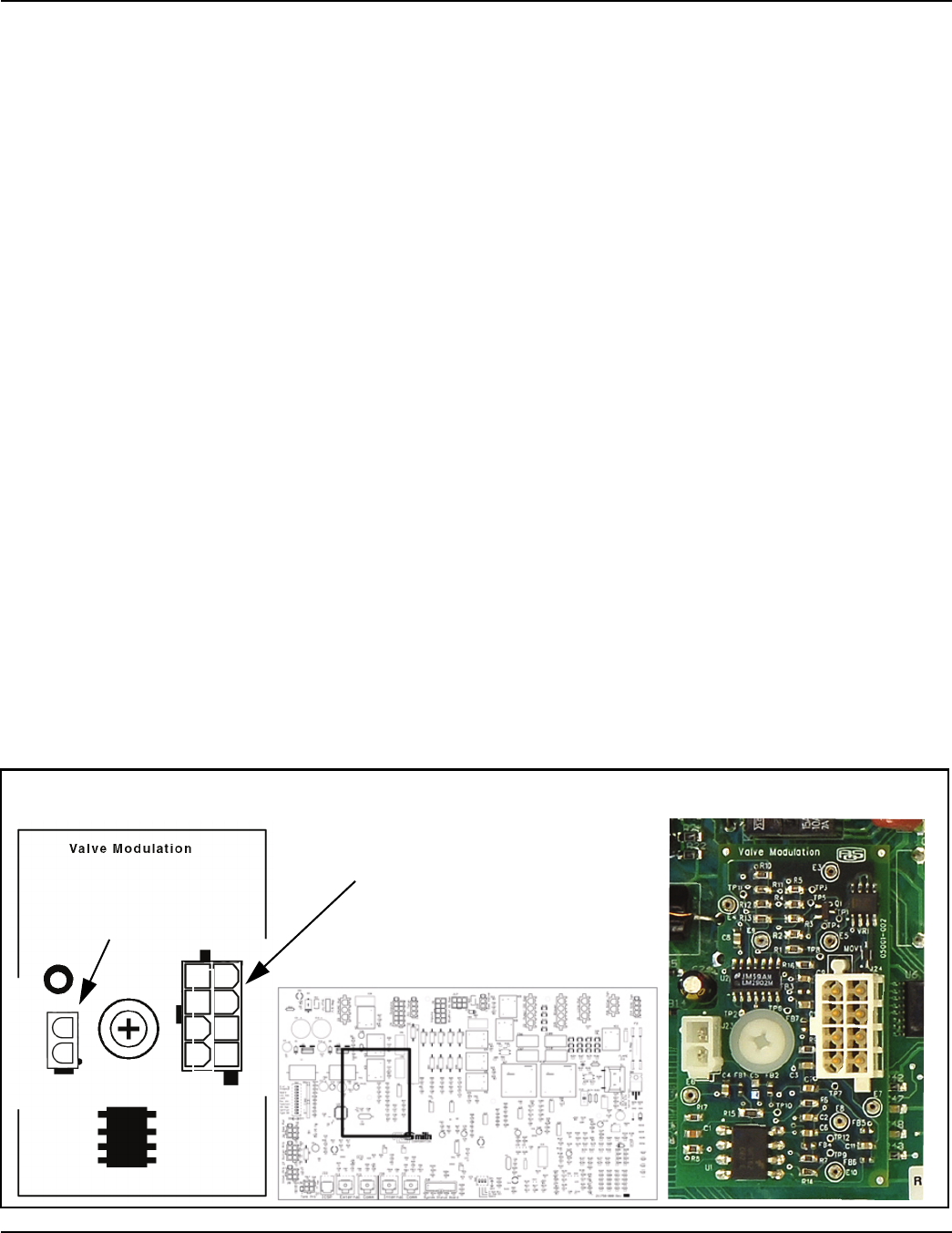
MCB SECTION H
This section of the MCB contains a small “Daughter Board” that contains the J23 and J24
sockets. Refer to page 25 for more information. The VFD (page 11), the Hall Effect sensor
(page 13) and the Config Key (page 14) connect to this Daughter Board.
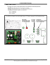
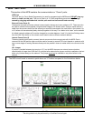
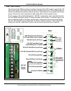
Service Notes: J24 Pins 1 and 2 (1-10 VDC VFD instruction) are polarity sensitive. If these
two wires are not connected as shown. The VFD will not start the blower. The pump on the
boiler will start but the blower will not. After 5 minutes the MCB will lock out and display the
“Sequence Err” error message.
J24 Pins 6, 7, and 8 connect to the Hall Effect sensor (page 13). There are spade
connections in the wiring chase for these three; red, blue, and black wires. The wire colors
must be connected as shown here. If these wires are not connected or cross connected (in
the wring chase) the MCB will read 0 rpm even though the blower is running. The control
system would then lock out and display the “Ignition Speed” error message.
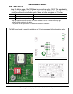
The MCB contains a resistor for the VFD enable/disable circuit to limit current. There is
approximately 1100 ohms resistance when this circuit has been closed by the MCB; use a
2000 to 20,000 ohm scale on the ohm meter being used. The audible continuity test feature
on most ohm meters is a max 200 ohms scale; this would incorrectly show an open circuit.
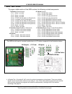
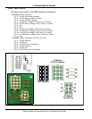
J23 Socket (Config Key)
• Pin 1 - Config Key
• Pin 2 - Config Key
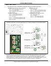
J24 Socket (VFD & Hall Effect Sensor)
• Pin 1 - VFD - Negative 1-10 VDC instruction - Black/White Stripe Wire
• Pin 2 - VFD - Positive 1-10 VDC instruction - Yellow /Red Stripe Wire
• Pin 3 - VFD - Enable/Disable Circuit - Red/White Stripe Wire
• Pin 4 - VFD - Enable/Disable Circuit - Blue/Black Stripe Wire
• Pin 5 - Not used
• Pin 6 - Hall Effect Sensor - Red Wire
• Pin 7 - Hall Effect Sensor - Blue Wire
• Pin 8 - Hall Effect Sensor - Black Wire
H
5
6
7
8
1
2
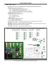
J23 Config Key
(modulation key
socket)
J24 Variable Frequency Drive (VFD)
and Hall Effect Sensor (blower rpm)
1
2
3
4
The MCB circuit board is mounted upside down on VF boilers compared to the illustrations below.