


VF BOILER SERVICE MANUAL
AOS WPC - Tech Training 26 of 72 Ashland City, TN © 2007
Servicing should only be performed by a Qualified Service Agent
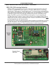
MCB - MODULATING CONTROL BOARD - OVERVIEW (CONT)
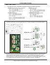
The MCB circuit board is the main controller. All instructions for burner modulation and
temperature control originate from this circuit board. Diagnostic and operational messages
are generated by the MCB and sent to the UIM. Most of the boiler’s components, such as
the igniter, blower, gas valve, and temperature probes are directly connected to one of the
MCB’s 16 socket connectors.
Wiring and connection details given here reference 100-101 Series VF boilers.
The wiring and connection information shown in this service manual are in reference to how
the EMC 5000 controls and circuit boards connect on VF boilers. This service manual
should be used as a reference for A. O. Smith VF boilers only.
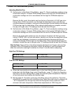
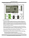
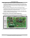
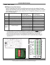
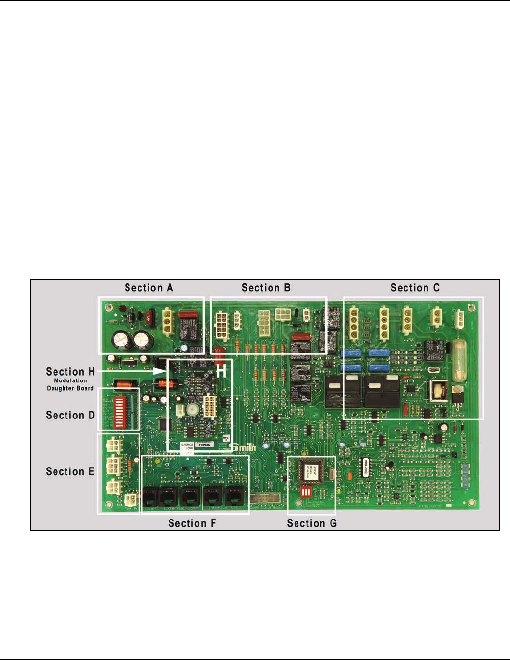
The MCB circuit board measures approximately 13” x 7” and has 16 Molex/AMP socket
connectors. The MCB circuit board has been divided into sections in the illustration below,
each section will be covered in the pages that follow.
IMPORTANT NOTE - MCB CIRCUIT BOARD ORIENTATION
The MCB circuit board is mounted upside down on VF boilers compared to the illustration
below. Keep this in mind when referencing the illustrations in this manual.
The pages that follow reference the MCB circuit board as oriented in this illustration.
The MCB board is physically mounted upside down inside the boiler cabinet compared to this illustration.