


AOS WPC - Tech Training 5 of 72 Ashland City, TN © 2007
Servicing should only be performed by a Qualified Service Agent
VF BOILER SERVICE MANUAL
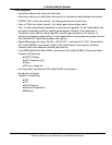
UIM - USER INTERFACE MODULE - OVERVIEW
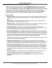
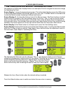
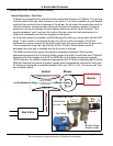
The UIM is an assembly that consists of several electronic components. The main circuit
board in the assembly is the UIB (User Interface Board) which houses the communications
port. The UIB relays user input and data to and from the MCB, controls the LCD, and
activates the LEDs. Mounted to the UIB is a TSB (Touch Sensor Board) containing the touch
sensor pads that are the user input buttons. There is a LCD module mounted to the UIB that
displays operational information and diagnostic messages in plain English.
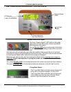
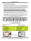
LEDs
(Light Emitting Diode)
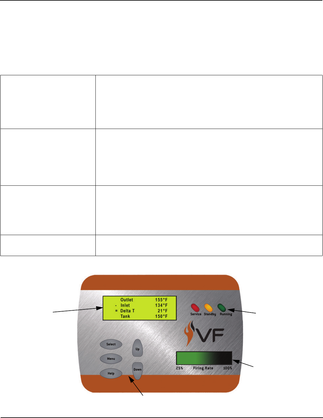
• Three “System Status” LED lights: Service, Standby, Running.
Located to the right of the LCD.
• Firing Rate Status indicator - located in the lower right portion of
the UIM. Four LED lights behind a green (gradient) translucent
cover. This display indicates the approximate firing rate
between 25% and 100%.
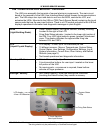
LCD
(Liquid Crystal Display)
• LCD display - 4 lines, up to 20 characters per line.
• 10 different screens - Menus, Temperatures, System Status,
Control States, User Settings, Configuration Settings, Log &
System Information, Current Error, Error History, and Reload
Defaults (see page 9).
• Text based operational and diagnostic information.
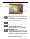
User Input Buttons • Select - Menu - Help - Up - Down.
• 5 touch sensitive buttons for user input. Located on the lower
left portion of the UIM.
• No moving parts - no pressure is required; these buttons
activate on finger presence.
Settings / Memory • Non volatile memory; once new settings are confirmed
(touching the Select button) they remain in memory.
LCD display
4 line x 20 character
Firing Rate Status
5 Touch Sensitive
User Input Buttons
System Status
LEDs