


VF BOILER SERVICE MANUAL
AOS WPC - Tech Training 24 of 72 Ashland City, TN © 2007
Servicing should only be performed by a Qualified Service Agent
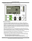
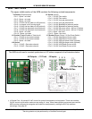
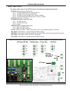
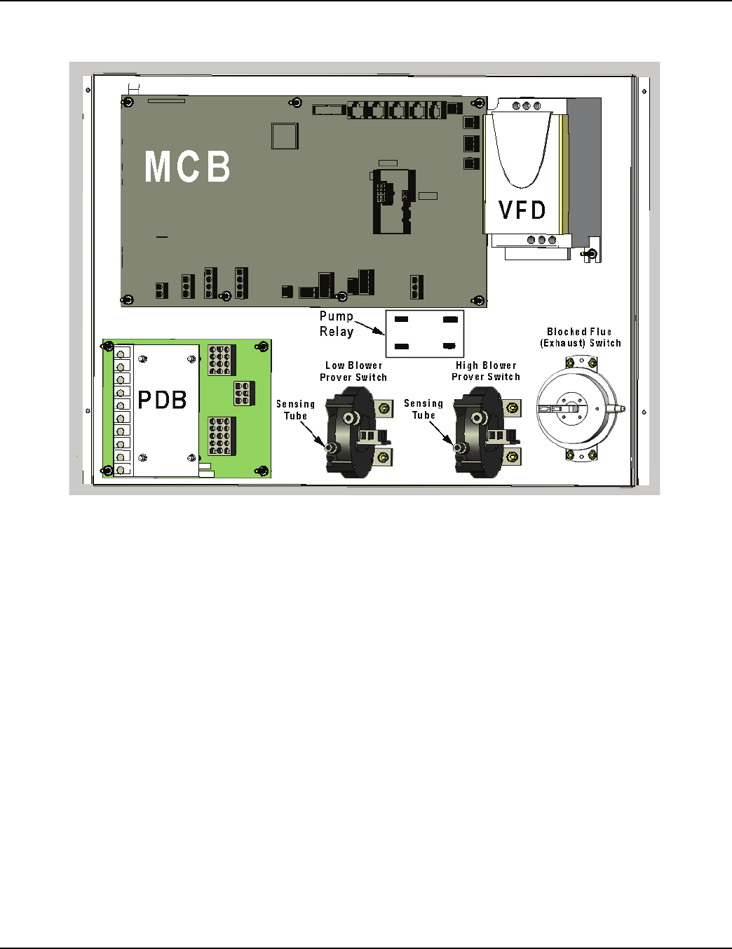
CONTROL PANEL LAYOUT
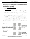
The illustration below shows the control panel on VF boilers.
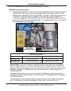
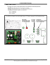
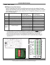
Blower Prover Switches
VF boilers are equipped with High and Low blower prover switches or BPS. Both are
normally open air pressure switches. Both close on a fall in pressure (a negative/vacuum
pressure). The contacts of both must be open at the beginning of each heating cycle. The
High BPS is only used when the boiler is in the Pre/Post Purge operating states (blower at
5000 rpm). The High BPS contacts must close during these two states only and must remain
open at all other times. The Low BPS must be closed whenever the blower is running. See
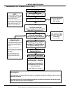
the Sequence of Operation on page 15.
Note which sensing ports are used. The two sensing ports on each pressure switch are
differentiated with the letters “L” and “H” embossed on the switch body. The sensing tubes
must be connected to the ports marked “L.” The other port remains open. The barbed fitting
for the “H” port is typically cut off at the factory to ensure proper connection.
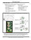
The two sensing tubes that connect to the blower prover switches are T fitted together and a
single tube from the T fitting then connects to a port on the gas train.
If the EMC 5000 control system is locked out and displays the “Blower Prov Stg1” error
message closely inspect the sensing tubes and wiring to the two blower prover switches.
• Ensure the sensing tubes are connected to the right ports.
• Ensure the sensing tubes are not kinked and securely connected at both ends.
• Ensure the two wires to each switch are connected to the wiring terminals marked C and NO.