


AOS WPC - Tech Training 47 of 72 Ashland City, TN © 2007
Servicing should only be performed by a Qualified Service Agent
VF BOILER SERVICE MANUAL
ERROR MESSAGES (CONT)
DISPLAYED MESSAGE
CONDITION/INDICATES
CHECK/REPAIR
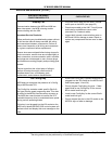
“No Flow”
Pump is Running
(If pump is not running go to the preceding page)
Normally open contacts on factory mounted flow
switch are not closing or are not remaining closed
after the pump is energized.
Water flow rate at the outlet of boiler is below the
activation point for the flow switch. Factory mounted
flow switch is a normally open and closes at
approximately 22 GPM. (GPM = gallons per minute).
Important Installation Note:
The combined total of supply and return water
piping must not exceed 50 equivalent feet on VF
boilers equipped with a “factory installed” pump.
Exceeding this limitation can and will cause “No
Flow” lock outs. Be certain all elbows and fittings in
the supply and return lines between the boiler and
the storage tank or heating loop are considered in
the equivalent feet calculations.
Installations that exceed the 50 equivalent foot
limitation described above require field supplied and
installed pumps that are properly sized.
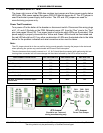
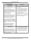
Operational Note:
Boiler outlet valves are often partially closed to
regulate flow rate and temperature rise through the
boiler. A bypass line with a throttling valve should be
installed between the inlet and outlet lines of the
boiler. Bypass valves are often partially open to
maintain inlet water temperature at or above 120°F.
Throttle outlet valve to achieve a 20 - 40°F
temperature rise through the boiler.
Throttle bypass valve to maintain minimum inlet
water temperature of 120°F before performing the
check/repair procedures here.
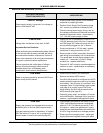
•
New boiler installations in older systems;
Check for restrictions in the water lines (accu-
mulated lime) to and from the boiler. System
lines can become restricted with lime and sedi-
ment accumulation over time and sometimes
must be replaced on older systems.
•
New boiler installations in older systems;
Ensure existing water lines to and from the
boiler are properly sized. Supply and return
lines to the boiler must not be smaller than the
inlet and outlet connections on the boiler. Exist-
ing water lines may be undersized (restrictive)
and need to be replaced.
• Ensure flow switch is wired correctly using the
Common and Normally Open contact terminals.
• De-lime boiler if necessary - lime accumulation
within the boiler (over time) can reduce flow.
• Ensure the boiler, supply/return lines, storage
tank, building loop, and all water system compo-
nents are purged of air.
• Check condition of flow switch and paddle -
replace worn or missing paddle - replace flow
switch if damaged or defective.
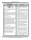
• Check temperature rise through the boiler
at
100% firing. Ensure ΔT is not above 40°F.
Check for partially closed valves that could lead
to reduced flow rate.
•
If ΔT at 100% firing is 20 - 40°F, adjust setting
screw on flow switch to close contacts while the
pump is running. If flow switch cannot be
adjusted to close contacts when temperature
rise/flow rate is correct - replace the flow switch.
• Turn off power to the boiler and
TEMPORARILY
INSTALL JUMPER WIRE
across the flow
switch wiring terminals. Turn power back on and
reset the control - see page 41.
If error message persists with jumper wire on -
call the A. O. Smith technical information center
for further assistance at 800 527-1953
REMOVE JUMPER WIRE FROM FLOW
SWITCH IMMEDIATELY AFTER PERFORM-
ING THIS TEST. FAILURE TO DO SO CAN
RESULT IN PROPERTY DAMAGE AND/OR
PERSONAL INJURY.