


VF BOILER SERVICE MANUAL
AOS WPC - Tech Training 52 of 72 Ashland City, TN © 2007
Servicing should only be performed by a Qualified Service Agent
ERROR MESSAGES (CONT)
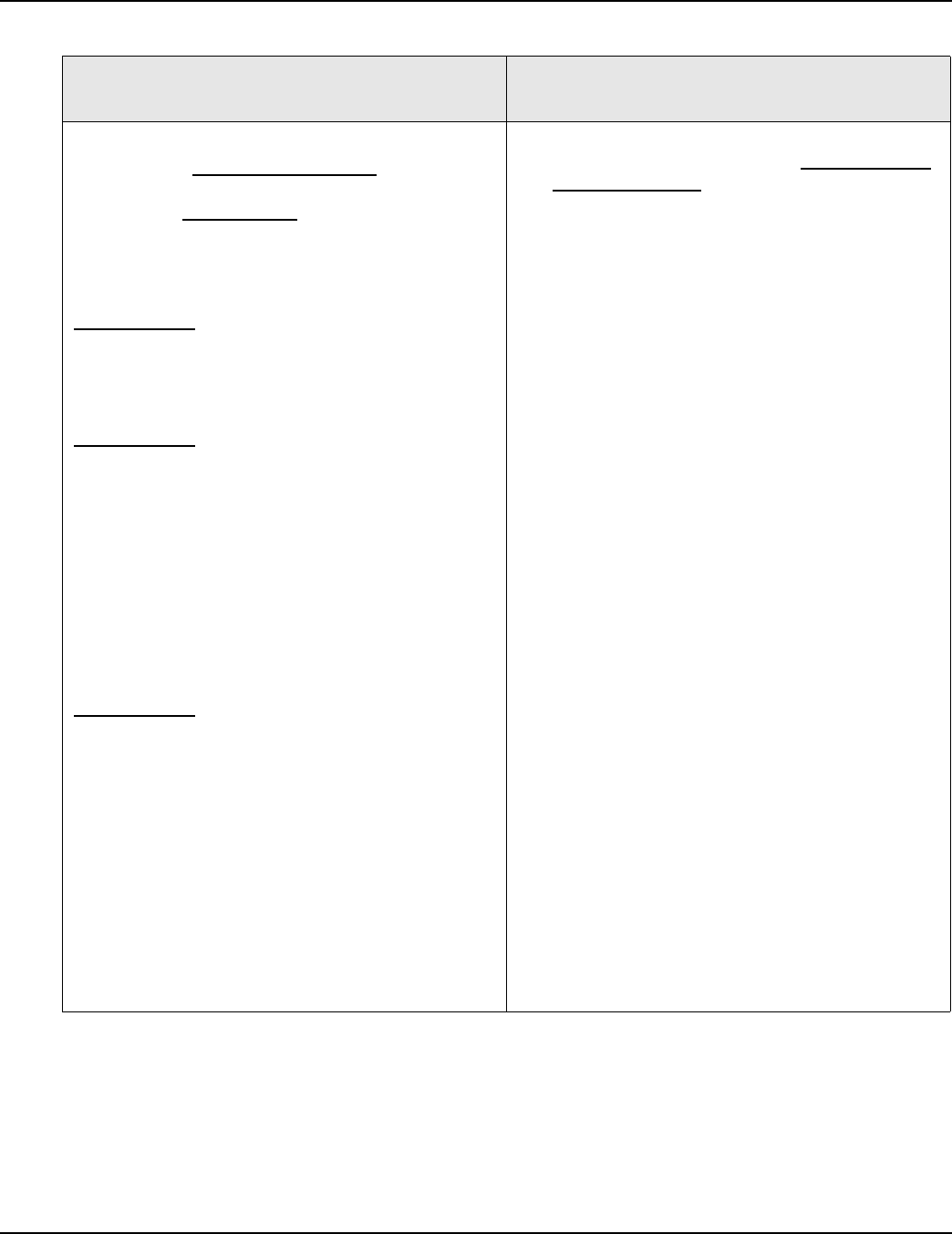
DISPLAYED MESSAGE
CONDITION/INDICATES
CHECK/REPAIR
“Blower Prov Stg1”
Blower Is Starting
(If the blower is not starting go to the “Blower Prov
Stg1” Blower Is Not Starting
tables)
Three conditions can cause this error message
when the blower is starting:
Normally Open Low Blower Prover or High Blower
Prover pressure switch contacts are not closing
during the pre or post purge operating states - or
within 5 minutes of call for heat being activated.
OR
Normally Open High Blower Prover pressure switch
contacts did not re-open after pre purge operating
state was completed. The High Blower Prover switch
is used to prove adequate purging of the combustion
chamber during pre and post purge cycles only. The
blower runs at approximately 5000 rpm during pre
and post purge operating states and at lower speeds
during all other operating states. High blower prover
switch contacts must close during the pre and post
purge states ONLY and open during all other
operating states.
OR
Normally Open Low Blower Prover pressure switch
contacts have opened during any operating state
when the blower should be running. IE: This can be
caused due to blower failure during the heating cycle
or if the pressure sensed by the switch rises above
the switches activation pressure for any reason. The
normally open contacts on both Blower Prover
switches close on a fall in pressure - the pressure
sensed must be in a vacuum.
Operational Note:
See blower prover switch information on page 24
and the Sequence of Operation on page 15.
• Ensure the sensing tubes are connected to the
“L” sensing ports on both BPS
(BPS = Blower
Prover Switches) see the control panel layout
and pressure switch information on page 24.
• Ensure all BPS sensing tubes are not kinked
and are properly connected. The two tubes from
the BPS are T fitted together and a single sens-
ing tube from this T fitting connects to a sensing
port on the gas train (the BPS sense manifold
gas pressure) - check/repair all connections.
• Ensure the blower motor wiring at the VFD
blower output terminals is wired correctly. The
blower motor wires are color coded; Black,
White, and Red. The proper connection points
on the VFD are shown on page 11. The blower
motor is 3 phase - incorrect wiring at the VFD
will cause the blower motor to run backwards
and cause this lock out condition.
• Ensure the gas train shut off valve between the
boiler’s 24 VAC gas valve and the Venturi is
open (see the image on page 23).
• Ensure the wiring to both BPS is properly con-
nected to the Com and N.O. terminals.
• Check all wiring between both BPS and the J17
socket on the MCB (page 28). Ensure the plug/
socket connectors are making good contact.
Replace/repair anything worn or damaged.
• Ensure the wiring to the Low BPS is coming
from MCB J17 pins 5 & 6 and the wiring to the
High BPS is coming from MCB J17 pins 1 & 2
see page 28.
• Ensure blower is operating at correct speed dur-
ing Igniter Warm Up period, Min Fire mode, and
Max Fire mode.
Perform Firing Rate - Modulation Performance
procedure described on pages 21 and 22.