


VF BOILER SERVICE MANUAL
AOS WPC - Tech Training 30 of 72 Ashland City, TN © 2007
Servicing should only be performed by a Qualified Service Agent
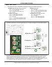
MCB - SECTION D
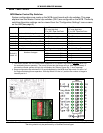
MCB Master Control Dip Switches
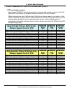
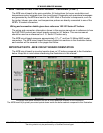
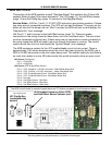
System configurations are made on the MCB circuit boards with dip switches. This page
explains how the Master Control dip switches (SW1) are configured on the MCB. These dip
switch/configuration settings can be viewed from the “Configuration Settings” menu screen
on the UIM (see page 9).
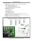
Switch 1 Type of boiler application On = VB
235° max high limit
70° to 220° Oper Set Point
Off = VW
210° max high limit
70° to 190° Oper Set Point
Switch 2 Number of trials for ignition On = 3 Off = 1
Switch 3 IRI gas valve - N/A set to “off” On = IRI gas valve present Off = IRI not present
Switch 4 Controlling probe On = Tank/Loop (Remote) Off = Inlet
Switch 5 Power vent kit - N/A set to “off” On = Yes Off = No
Switch 6 Low water cut off present On = Yes Off = No
Switch 7 Low gas pressure switch present On = Yes Off = No
†
Switch 8
†. The control system will not initiate blower operation on VF boilers if dip switch 8
IS NOT set to “on”
for modulating burner operation. The pump will start but the blower will not. After approximately 5
minutes the control system will lock out and display the “Blower Prover Stg 1” error message.
Firing Mode On = Single Modulating Burner Off = Multi-Stage Burners
‡
Switch 9
Switch 10
‡. Stage configuration dip switches 9 & 10 are disregarded by the MCB when dip switch 8 is set to “on”
for single modulating burner operation. With dip switch 8 in the “on” position the number of stages is
internally set to 1.
Number of stages
Switch 9 Switch 10
Off Off 1 stage
Off On 2 stage
On Off 3 stage
On On 4 stage
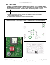
D
10
9
8
7
6
5
4
3
2
1
Firing Mode