


VF BOILER SERVICE MANUAL
AOS WPC - Tech Training 50 of 72 Ashland City, TN © 2007
Servicing should only be performed by a Qualified Service Agent
ERROR MESSAGES (CONT)
DISPLAYED MESSAGE
CONDITION/INDICATES
CHECK/REPAIR
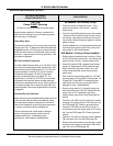
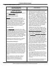
“Blower Prov Stg1”
Blower IS NOT Starting
(If the blower is starting proceed to the “Blower Prov
Stg1” Blower Is Starting
tables)
IMPORTANT SERVICE NOTE:
BEFORE performing any of the check/repair
procedures in the right column of this table; review
the VFD and Blower Operation section in this
manual on page 11. Also review the Config Key
information on page 14 and the VFD/MCB
connections and service notes contained on page
34. Understanding how the MCB and VFD work
together to operate the blower is necessary.
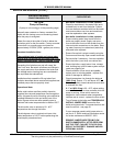
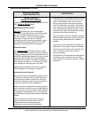
Operational Note:
If the Normally Open Low Blower Prover or High
Blower Prover pressure switch contacts (circuits) are
closed at the beginning of the heat sequence prior to
the MCB initiating blower operation for the pre purge
operating state; the MCB will not initiate blower
operation in this condition - the MCB will declare a
fault condition and lock out. The “Blower Prov Stg1”
error message will be displayed on the UIM.
See blower prover switch information on page 24
and the Sequence of Operation on page 15
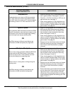
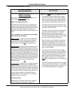
Important Service Reminder:
When performing any troubleshooting steps outlined
in this service manual always consider the wiring
and connectors between components. Perform a
close visual inspection of all wiring and connectors
to a given component before replacement. Ensure
wires were stripped before being crimped in a wire
connector, ensure wires are crimped tightly in their
connectors, ensure connection pins in sockets and
plugs are not damaged or worn, ensure plugs and
sockets are mating properly and providing good
contact.
Failure to perform this critical step or failing to
perform this step thoroughly often results in
needless down time, unnecessary parts
replacement, and customer dissatisfaction.
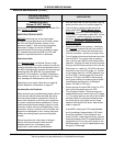
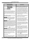
• Ensure all wiring is reconnected to the VFD and
all plugs are securely plugged into the MCB/
PDB. With power on and a call for heat acti-
vated check for a 1-10 VDC instruction from the
MCB at VFD low voltage terminals “0V” and
“AI1” - see VFD connections on page 11. See
also the Firing Rate - Modulation Performance
section on page 21 and VFD Operating Param-
eters section on page 22. Ensure you are using
a “DC” volt meter for this test. At the beginning
of a heat sequence (during pre purge) there
should be 8-9 VDC measured at these two ter-
minals. If there is not any DC voltage measured
- check/repair all wiring, sockets, and plugs
between the VFD and pins 1 & 2 of the J24
socket on the MCB see page 34.
• Check blower motor output voltage from the
VFD. This is a 3 phase power supply see page
11. With power on and a call for heat activated
perform three AC voltage checks
at the begin-
ning of the heat sequence (ensure meter is set
for AC voltage). Check between VFD Blower
Output terminals; U/T1 & V/T2
, U/T1 & W/T3,
and V/T2 & W/T3
. Actual AC voltages measured
may be between 90 and 240 VAC. The actual
amount of voltage is not important within this
range. However, all three readings should be
within 10% of each other. If no voltage is mea-
sured during any of the three voltage checks or
if any one or two measurements were signifi-
cantly lower AND all other MCB/VFD test results
above were successful - replace the VFD.
• If the VFD output to blower motor test above
showed consistent voltage between 90 and 240
AC volts during all three checks and the blower
motor still does not start - check all wiring
between the VFD blower output terminals and
the blower motor. Repair/replace any worn or
damaged wiring.
• If all wiring to blower motor from the VFD is in
good condition and the blower will not start with
correct AC voltage applied: Ensure the blower
motor IS NOT hot to the touch. If the blower
motor is cold to the touch at this point - replace
the blower.
If the motor is hot to the touch at this point pro-
ceed to the next check/repair procedure.