


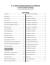

AOS WPC - Tech Training 9 of 72 Ashland City, TN © 2007
Servicing should only be performed by a Qualified Service Agent
VF BOILER SERVICE MANUAL
UIM - USER INTERFACE MODULE - MENU SCREENS
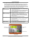
At the top center of the UIM panel is the display LCD. This LCD is used to provide
information to the user through menu activated screens. Within each of the screens, helpful
context sensitive information can be displayed at any time by touching the “Help” button.
Touching the help button once more returns the user to the previous screen.
The 10 available screens are:
Menu Screen:
Displayed when the “Menu” button is touched. This screen is the selection point for the other
menu screens.
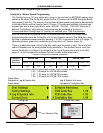
Temperatures Screen (Default Screen):
Displays the temperatures sensed from the Outlet, Inlet, and optional remote Tank/Loop
temperature probes. This screen also displays the calculated temperature rise (Outlet minus
Inlet) through the boiler, sometimes referred to as the Delta T (ΔT). Shorted and
disconnected probes will have “Short” and “----” displayed to the right. The Temperatures
Screen is the default screen the boiler will come to rest at without any user input for
approximately 60 seconds.
There are no adjustable user inputs available from this screen.
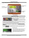
System Status Screen:
This screen is used to view the status of switch inputs and output states. An asterisk (*) is
displayed next to the label when the status is “True” (the description is fulfilled). For
example; if water is flowing, as detected by the flow switch, an asterisk (*) will appear in front
of the Flow label (IE: *Flow).
There are no adjustable user inputs available from this screen.
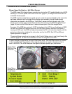
Control States Screen:
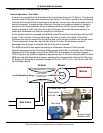
The CCB/FCB operating states of the boiler are displayed in this menu screen along with the
actual blower motor rpm as relayed from a Hall Effect sensor (page 13) located inside the
end cap of the blower motor. Blower rpm are displayed in real time. CCB and MCB are the
same component on VF Boilers. See explanation for this and the FCB term on page 25.
There are no adjustable user inputs available from this screen.
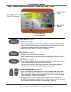
User Settings Screen:
This screen is used to enter values for various user settings such as; the operating set point
abbreviated Oper Setpnt, the Hi Limit (automatic high limit), pump post circulate time etc.
The Select button must be touched once to activate the adjustment mode for a user setting
and again to confirm and store the new setting into memory.
Configuration Settings Screen
Displays the status of the SW1 and SW2 dip switches (pages 30 and 33) on the MCB.
There are no adjustable user inputs available from this screen.