


VF BOILER SERVICE MANUAL
AOS WPC - Tech Training 40 of 72 Ashland City, TN © 2007
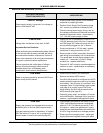
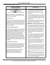
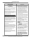
Servicing should only be performed by a Qualified Service Agent
PDB - POWER SUPPLY TEST
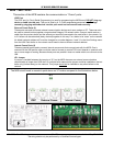
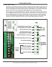
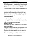
The lower right corner of the PDB also contains two jumpers and three power supply status
LED lights. With power applied the green DS2 LED should always be lit. The JP1 jumper is
used to activate a power supply test function. The JP2 and JP3 jumpers are used for
manufacturing purposes only.
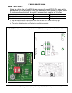
Power Test Procedure:
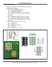
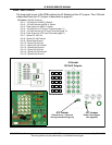
Turn power off to the boiler at the breaker or disconnect switch. Disconnect the wiring plugs
at J1, J2, and J3 Sockets on the PDB. Relocate jumper JP1 from the “Run” pins to the “Test”
pins (see pages 38 and 39). Turn power back on and note which LEDs are illuminated. If the
power supply is properly connected the Yellow and Green LEDs should be illuminated and
the red LED should be off. If any other combination of LEDs are illuminated refer to the table
below for the problem indicated and what corrective action must be taken.
Note:
The JP1 jumper should be in the run position during normal operation. Leaving the jumper in the test mode
when operating the system may cause trouble with Ground Fault Interrupters.
The wire harnesses that normally connect to J1, J2, & J3 should be disconnected while performing this test.
Leaving them connected will not cause damage but the status indicated by the LED's will be incorrect.
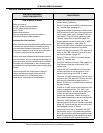
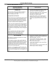
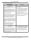
LINE CONNECTION STATUS DS1 YELLOW LED DS2 GREEN LED DS3 RED LED
Proper Connection ON ON OFF
Open Ground OFF ON OFF
Reverse Polarity OFF ON ON
Open Hot OFF OFF OFF
Open Neutral ONONON
Reverse Hot & Ground ON OFF ON
Hot wire on Neutral connect & Open
Neutral wire
OFF OFF ON
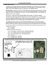
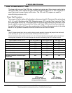
D
DS1
Yellow
DS2
Green
DS3
Red
JP1
JP3 Jumper
Should be on - removed
during manufacturing only
Test
Run
JP1 Jumper
Power Test Jumper