


VF BOILER SERVICE MANUAL
AOS WPC - Tech Training 42 of 72 Ashland City, TN © 2007
Servicing should only be performed by a Qualified Service Agent
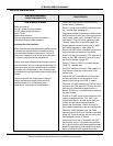
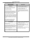
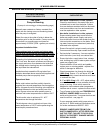
ERROR MESSAGES
DISPLAYED MESSAGE
CONDITION/INDICATES
CHECK/REPAIR
UIM Display Is Blank
Boiler is turned off
120 VAC power supply problems
24 VAC power supply problems
Blown Fuses
Defective transformer
Wiring or plug/socket connection problems
UIM communication cable problems
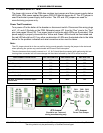
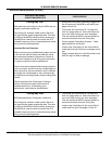
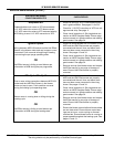
Important Service Reminder:
When performing any troubleshooting steps outlined
in this service manual always consider the wiring
and connectors between components. Perform a
close visual inspection of all wiring and connectors
to a given component before replacement.
Ensure wires were stripped before being crimped in
a wire connector, ensure wires are crimped tightly in
their connectors, ensure connection pins in sockets
and plugs are not damaged or worn, ensure plugs
and sockets are mating properly and providing good
contact.
Failure to perform this critical step or failing to
perform this step thoroughly often results in
needless down time, unnecessary parts
replacement, and customer dissatisfaction.
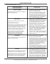
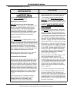
• Ensure the on/off switch is on and working -
replace switch if defective.
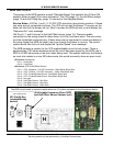
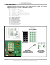
• Ensure 7.5 amp fuse on MCB is not blown/miss-
ing - replace fuse (see page 27).
• Check comm cable connections at UIM and the
MCB’s Internal Comm Ports. Secure power and
install a new comm cable. (standard Cat 5 net-
work cable). Plug UIM comm cable into other
“internal” comm port on the MCB (page 32).
• Closely inspect communication ports on MCB
and UIM for damage or wear (page 32).
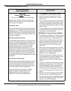
• Ensure 120 VAC power is properly connected in
the junction box on the back of the boiler.
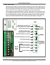
• Ensure 120 VAC is supplied to TB1 terminals 8
and 9 on the PDB. Hot wire to terminal 8, neu-
tral wire to terminal 9 (page 36).
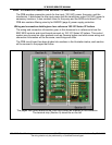
• Ensure F7 fuse on PDB is not blown/missing
(page 37) - replace fuse.
• Check F3 transformer fuse on PDB (page 37) if
fuse is blown check wiring for shorts - then
replace fuse.
• Check 120 VAC to transformer at the primary
winding terminals on the transformer. If not
present check wiring from PDB J1 socket.
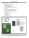
• Check for 120 VAC between pins 3 & 6 of the J1
socket on the PDB (page 38). Perform this test
with the wiring harness plugged into the J1
Socket. Ensure the J1 socket and plug are mak-
ing good contact.
• Check for 24 VAC output at the transformer sec-
ondary winding terminals - if 24 VAC is not
present AND the two checks above were per-
formed and the results were successful -
replace the transformer. Check all wiring for
shorts before powering up the new transformer.
• Check for 24VAC between pins 1 & 2 and
between pins 4 & 5 of the J1 Socket on the PDB
(page 38). Perform this test with the wiring har-
ness plugged into the J1 Socket.
• Ensure the pins in the J1 socket on the PDB
and the pins in the J1 plug and wiring harness
are in good condition and making good contact.
Repair or replace any parts that are worn, dam-
aged, or failing to make a good connection.