


VF BOILER SERVICE MANUAL
AOS WPC - Tech Training 62 of 72 Ashland City, TN © 2007
Servicing should only be performed by a Qualified Service Agent
BOILER CONTROLS (CONT)
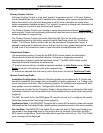
Primary System Control
A Primary System Control is a top level “system” temperature control. A Primary System
Control activates the call for heat or enables boiler operation when system temperature falls
below the control’s set point and deactivates a call for heat or disables the boiler when
system temperature reaches set point. The “system” is typically a storage tank (domestic hot
water supply) or a hydronic loop (building heat system).
The Primary System Control must be able to sense temperature conditions in the system to
work properly. It must not be adversely affected by false heat such as heat added by multiple
boilers upstream or a bypass line.
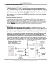
The Primary System Control can be the Operating Set Point on the boiler acting on
temperature sensed by the factory supplied remote Tank/Loop probe; the “Controlling
Probe.” The Primary System Control can also be an External Temperature Control; a
separate mechanical or electronic device that will have it’s own system temperature sensor
(s) and a set of dry contacts to close or open the boiler’s Enable/Disable circuit.
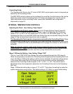
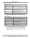
Temperature Probes
The temperature probes (3) used by the EMC 5000 control system are thermistors.
Thermistors are thermally sensitive resistors. A change in temperature causes a
corresponding change in electrical resistance (ohms). The EMC 5000 control system
interprets the probe resistance as temperature.
VF boilers have two factory installed temperature probes; an Inlet Probe and an Outlet
Probe to monitor the inlet and outlet water temperatures.
VF boilers are shipped from the factory with a third probe; the remote Tank/Loop Probe.
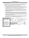
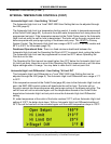
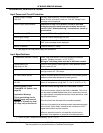
Remote Tank/Loop Probe
Installation/Configuration:
Remote Tank/Loop probes are furnished with VF boilers and
should be installed in the storage tank on domestic hot water systems or in a T fitting in the
return line before the boiler’s inlet on heating systems. On multiple boiler systems all Tank/
Loop probes must be installed in T fittings before the first boiler’s inlet.
Two wires are provided for the Tank/Loop Probe in the junction box on the back of the boiler.
Dedicated conduits must be provided for the field installed wiring to each Tank/Loop probe
(page 68).
The SW1 dip switch #4 on the MCB (page 30) must be turned “on” to configure the remote
Tank/Loop probe as the Controlling Probe (page 63).
Application Note: If the MCB SW1 dip switch #4 is turned off the control system will use the
Inlet probe as the Controlling Probe; reliable system temperature control will not be possible.
Service Note: If the MCB SW1 dip switch #4 is turned on and the Tank/Loop Probe is not
connected to the designated wires in the junction box on the back of the boiler the EMC
5000 control will declare a Tank Probe failure/fault condition and lock out. The “Tank Probe”
error message will be displayed.