VF BOILER SERVICE MANUAL
AOS WPC - Tech Training 58 of 72 Ashland City, TN © 2007
Servicing should only be performed by a Qualified Service Agent
ERROR MESSAGES (CONT)
DISPLAYED MESSAGE
CONDITION/INDICATES
CHECK/REPAIR
“Flame Stg1” (cont)
Flame or ignition failure.
Error message displayed after 1 or 3 losses of flame
or after 1 or 3 failed trials for ignition. EMC 5000
control system will lock-out after 1 or 3 trials
depending on the SW1 #2 dip switch setting on the
MCB circuit board. (see page 30)
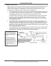
Important Service Reminder:
When performing any troubleshooting steps outlined
in this service manual always consider the wiring
and connectors between components. Perform a
close visual inspection of all wiring and connectors
to a given component before replacement.
Ensure wires were stripped before being crimped in
a wire connector, ensure wires are crimped tightly in
their connectors, ensure connection pins in sockets
and plugs are not damaged or worn, ensure plugs
and sockets are mating properly and providing good
contact.
Failure to perform this critical step or failing to
perform this step thoroughly often results in
needless down time, unnecessary parts
replacement, and customer dissatisfaction.
• Check igniter amperage during igniter warm up
period. If amp draw is less than 3.0 amps
replace the igniter.
• Ensure the 1/8” steel sensing tube that connects
between the gas valve (near the low fire adjust-
ment screw cap) and the Venturi assembly is
not clogged or damaged and properly con-
nected at both ends. If the tube is kinked or
damaged - replace the tube. Remove the steel
tube and blow through it to ensure it is not
clogged. Reinstall and tighten the compression
fittings tightly at both ends.
• Ensure the 24 VAC gas valve is being energized
during ignition:
If the burner is failing to ignite when viewed
through the view port on the top of the heat
exchanger - check for 24 VAC between pins 1 &
2 of the J19 socket on the MCB (page 28) at the
end of the igniter warm up period. If 24 VAC is
present - check all wiring between the J19
socket and the gas valve. Check the J19 socket/
plug pins for wear or damage. Check the ground
(green) wire from gas valve coil to the ground
connections in the junction box on the boiler -
repair/replace anything worn or damaged.
If 24 VAC is not present between pins 1 & 2 of
the J19 socket on the MCB - call the A. O. Smith
technical information center for further assis-
tance at 800 527-1953.


