


AOS WPC - Tech Training 57 of 72 Ashland City, TN © 2007
Servicing should only be performed by a Qualified Service Agent
VF BOILER SERVICE MANUAL
ERROR MESSAGES (CONT)
DISPLAYED MESSAGE
CONDITION/INDICATES
CHECK/REPAIR
“Flame Stg1”
Flame or ignition failure.
Error message displayed after 1 or 3 losses of flame
or after 1 or 3 failed trials for ignition. EMC 5000
control system will lock-out after 1 or 3 trials
depending on the SW1 #2 dip switch setting on the
MCB circuit board. (see page 30)
Important Service Reminder:
When performing any troubleshooting steps outlined
in this service manual always consider the wiring
and connectors between components. Perform a
close visual inspection of all wiring and connectors
to a given component before replacement.
Ensure wires were stripped before being crimped in
a wire connector, ensure wires are crimped tightly in
their connectors, ensure connection pins in sockets
and plugs are not damaged or worn, ensure plugs
and sockets are mating properly and providing good
contact.
Failure to perform this critical step or failing to
perform this step thoroughly often results in
needless down time, unnecessary parts
replacement, and customer dissatisfaction.
• Ensure the supply gas shut off valve to the
boiler and the gas train shut off valve (see
image on page 23) are both open.
• Perform the Start Up Procedure pages 17-19.
• Perform the Poor Combustion/Ignition Problems
procedures on pages 20-23.
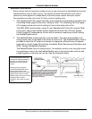
• View the burner through the view port near the
igniter on the top of the combustion chamber
during the ignition trial period. If the burner is
igniting but the flame goes out in a few seconds
ensure the flame sensor wiring is connected
properly and in good condition.
Note: There are two flame sensors on VF boil-
ers. A single wire is connected to the J16 con-
nect on the MCB (page 29). This wire is
bifurcated (divided) into two wires and each end
then connects to one of the two flame sensors.
Repair/replace any worn or damaged wiring.
• If the flame sensor wiring is in good condition -
perform a flame sensing test. Using a DC micro
amp meter; place the meter test probes in
series with the flame sensor wire. Disconnect
the wire at the J16 connect on the MCB (page
29) insert the tip of one test probe into the wire
connector securely - touch and hold the other
test probe to the J16 connect.
Measure the flame sensing current during igni-
tion. If the flame sensing current is less than 2.5
µA - remove, inspect, and clean both flame sen-
sors. 5.0 µA flame sensing current is typical.
If either flame sensor shows signs of damage or
the ceramic insulator is cracked - replace the
flame sensor (s). If the flame sensors are in
good condition clean both sensors with fine
steel wool and reinstall both sensors. Check
flame sensing current again to see if the current
is higher and burner flame is established.
If the burner flame is still going out after a few
seconds and all the above checks and proce-
dures have been performed - call the A. O.
Smith technical information center for further
assistance at 800 527-1953.