


AOS WPC - Tech Training 29 of 72 Ashland City, TN © 2007
Servicing should only be performed by a Qualified Service Agent
VF BOILER SERVICE MANUAL
MCB - SECTION C
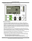
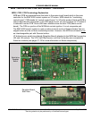
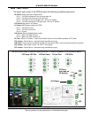
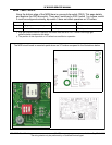
The upper right corner of the MCB contains the following sockets/components:
J2 Socket (Pump relay coil; IRI gas valve)
• Pin 1 - 120 VAC switched hot wire to pump relay coil
• Pin 2 - 120 VAC neutral wire to pump relay coil
• Pin 3 - 120 VAC hot wire to IRI gas valve - N/A on VF boilers.
• Pin 4 - 120 VAC neutral wire to IRI gas valve - N/A on VF boilers.
J15 Socket Not used on VF boilers
J1 Socket (MCB power supply from PDB)
• Pin 1 - 120 VAC hot wire
• Pin 2 - 120 VAC neutral wire
• Pin 3 - Ground
J18 Socket (Silicon Carbide igniter power)
• Pin 1 - Igniter 120 VAC hot wire
• Pin 2 - Igniter 120 VAC neutral wire
F2 Fuse - N/A on VF boilers - if fuse is removed or blown it will not effect operation of VF boiler
JP4 Jumper - Should be on - removed during manufacturing only
J16 Flame - Flame sensor connection (single wire connect on MCB - split wire serves two flame sensors)
JP2 Jumper - Set jumper on pins 1 & 2 for 2.7 amp igniter
JP3 Jumper - Should be on - removed during manufacturing only
C
J2 Pump / IRI Gas J1 Line Pwr J18 SiCarJ15 Not Used
4
3
2
1
4
3
2
1
3
2
1
2
1
3
2
1
F2 Fuse
not used on
VF boilers
J16 Flame
JP2
JP3
JP4
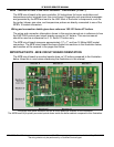
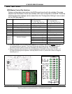
The MCB circuit board is mounted upside down on VF boilers compared to the illustrations below.
1
2
3