


AOS WPC - Tech Training 31 of 72 Ashland City, TN © 2007
Servicing should only be performed by a Qualified Service Agent
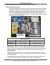
VF BOILER SERVICE MANUAL
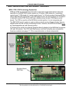
MCB - SECTION E
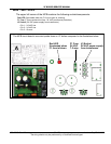
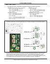
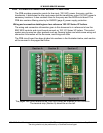
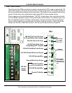
The lower left corner of the MCB contains the following sockets/components:
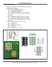
J6 Socket (Gas valve relay - N/A on VF boilers)
• Pin 1 - 24 VDC gas valve relay circuit
• Pin 2 - N/A - plug is filled
• Pin 3 - 24 VDC gas valve relay circuit
• Pin 4 - Ground
J7 Socket (Outlet probe)
• Pin 1 - 24 VDC manual reset ECO
• Pin 2 - 24 VDC manual reset ECO
• Pin 3 - Not used
• Pin 4 - 0 - 5 VDC outlet temperature probe
• Pin 5 - 0 - 5 VDC outlet temperature probe
• Pin 6 - Not used
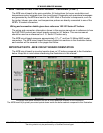
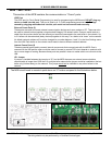
† J9 Socket Pins 3 & 4 - the remote Tank/Loop temperature probe connects to this socket. Two wires from this
socket are routed to the junction box on the back of the boiler. Dedicated field wiring and conduit must be
routed between the Tank/Loop probe and the junction box. The remote Tank/Loop temperature probe is
factory supplied with VF boilers. This temperature probe is used as the “Controlling Probe” (pages 62 and 63)
on VF boilers. SW1 dip switch #4 must be turned on to activate the this probe - see page 30.
E
1
2
3
4
5
6
1
2
4
2
3
1
3
4
1
2
3
4
J7 Outlet Prb
J9 Tank Prb
J8 Inlet Prb
J6 Gas Pwr
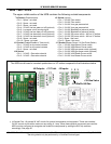
The MCB circuit board is mounted upside down on VF boilers compared to the illustrations below.
J8 Socket (Inlet probe)
• Pin 1 - Not used
• Pin 2 - 0 - 5 VDC inlet temperature probe
• Pin 3 - 0 - 5 VDC inlet temperature probe
• Pin 4 - N/A - plug is filled
†
J9 Socket (Remote Tank/Loop probe)
• Pin 1 - N/A - plug is filled
• Pin 2 - Not used
• Pin 3 - 0 - 5 VDC Tank/Loop probe
• Pin 4 - 0 - 5 VDC Tank/Loop probe