


AOS WPC - Tech Training 23 of 72 Ashland City, TN © 2007
Servicing should only be performed by a Qualified Service Agent
VF BOILER SERVICE MANUAL
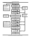
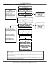
POOR COMBUSTION - IGNITION PROBLEMS (CONT)
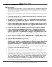
Manifold Gas Pressure Check
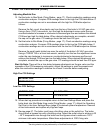
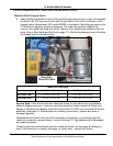
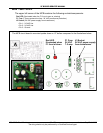
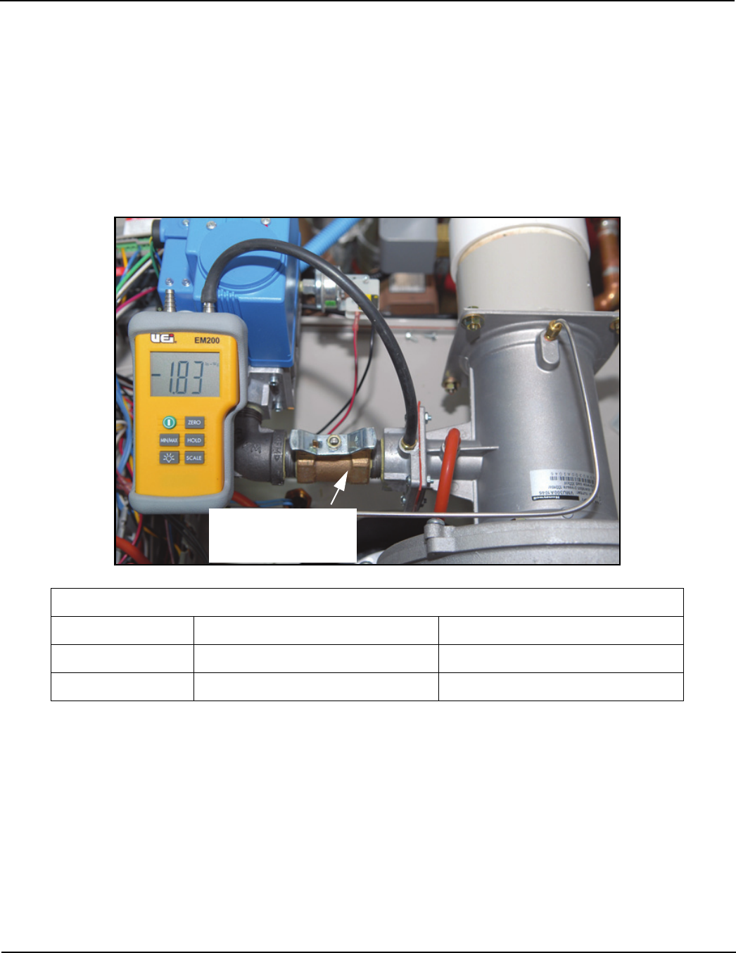
5. Attach Digital manometer to one of the manifold gas pressure taps on gas line between
the boiler’s 24 VAC gas valve outlet and the gas inlet on the Venturi as shown in the
images below. Recommend UEI model EM200 or equivalent. Manifold gas pressure on
VF boilers is a negative (vacuum) pressure. The lower the pressure (deeper the
vacuum) the higher the firing rate will be. Measure the manifold gas pressure with the
boiler firing in Max Mode and Min Mode (page 17). Manifold pressures should fall within
the ranges listed in the table below.
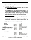
Service Note: If the actual pressures observed during the test above are considerably
different (higher pressures - closer to a positive pressure) closely inspect all fittings and
flanges in the gas train between the outlet of the boiler's 24 VAC gas valve and the Venturi
assembly. See page 12. Reseal/repair any leaking connections - replace any worn or
damaged gaskets.
Disassemble the Venturi from the inlet connection at the blower (round flange) and the
intake air connection (square flange) - ensure the large “O” ring gaskets are not damaged
and seating properly.
Closely inspect the cone shaped restrictor inside the Venturi for any signs of damage or
wear. If the restrictor is missing, damaged, or visibly worn - replace the Venturi.
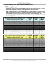
MANIFOLD PRESSURE
MAX MODE - 100% FIRING MIN MODE - 25% FIRING
NATURAL GAS
-1.5" W.C. to -4.0" W.C. -0.15" W.C. to -1.0" W.C.
PROPANE GAS -1.5" W.C. to -4.0" W.C. -0.15" W.C. to -1.0" W.C.
Venturi
Gas Valve
Gas Train
Shut Off Valve
Blower