


AOS WPC - Tech Training 45 of 72 Ashland City, TN © 2007
Servicing should only be performed by a Qualified Service Agent
VF BOILER SERVICE MANUAL
ERROR MESSAGES (CONT)
DISPLAYED MESSAGE
CONDITION/INDICATES
CHECK/REPAIR
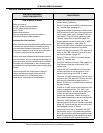
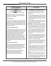
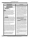
“Low AC Voltage”
Power supply polarity is reversed. Line voltage to
boiler is less than 90 VAC.
• Ensure power supply polarity is not reversed
and boiler is properly grounded.
• Perform Power Supply Test Procedure (page
40) - correct any problems indicated by test.
• Check incoming power supply, wiring, and all
line voltage connections on the boiler and at the
breaker or disconnect switch - repair/restore
115 - 120 VAC power supply to boiler.
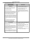
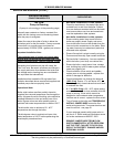
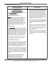
“Low 24 VAC”
Voltage from transformer is less than 18 VAC.
Important Service Reminder:
When performing any troubleshooting steps outlined
in this service manual always consider the wiring
and connectors between components. Perform a
close visual inspection of all wiring and connectors
to a given component before replacement.
Failure to perform this critical step or failing to
perform this step thoroughly often results in
needless down time, unnecessary parts
replacement, and customer dissatisfaction.
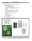
• Check 120 VAC to transformer. Check for 115 -
120 VAC between pins 3 & 6 of the J1 socket on
the PDB (page 38). Perform this test with the
wiring harness plugged into the J1 Socket.
• Ensure transformer is 100 VA rated - replace
transformer if rating is less than 100 VA.
• Secure power to boiler; temporarily disconnect
load wiring from secondary coil on transformer.
Turn power back on and check voltage at sec-
ondary coil - if secondary (24 VAC) voltage
remains low - replace transformer.
• Check all 24 VAC wiring for worn/damaged con-
nections or wires - replace/repair as necessary.
• Replace transformer.
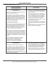
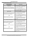
“Low Water”
Water is not being sensed by optional LWCO (low
water cutoff) device’s sensor.
• Ensure there is water in the lines/boiler.
• Remove and clean LWCO sensor.
• If the SW1 #6 dip switch is configured for LWCO
present when the optional control is not installed
on the boiler. This will return a “Low Water” error
message. Check “Config Settings” menu screen
(see page 9) to confirm correct LWCO dip
switch setting. Set SW1 #6 dip switch on the
MCB correctly (see page 30).
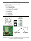
• Check all wiring, plugs, and sockets (J4 socket
on the MCB board - see page 28) for good con-
nections - repair/replace damaged/worn parts.
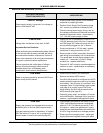
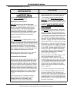
“Low Gas”
Supply gas pressure has dropped below pressure
activation point of the Low Gas Pressure switch.
Low gas pressure switch is standard on VF boilers.
SW1 dip switch #7 is set to “on” to configure the
control system to monitor this switch (page 30).
• Check supply gas pressure with boiler firing at
100%. Ensure supply pressure is maintained
above 4.0" W.C. for natural gas and 6.4" W.C.
for propane - replace low gas switch if supply
pressures are maintained above activation point
at 100% firing rate and error message persists.
• Ensure gas line is properly sized. - adjust gas
supply pressure at regulator serving the boiler.