


VF BOILER SERVICE MANUAL
AOS WPC - Tech Training 46 of 72 Ashland City, TN © 2007
Servicing should only be performed by a Qualified Service Agent
ERROR MESSAGES (CONT)
DISPLAYED MESSAGE
CONDITION/INDICATES
CHECK/REPAIR
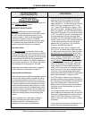
“No Flow”
Pump IS NOT
Running
(If pump is running proceed to the next page)
Normally open contacts on factory mounted flow
switch are not closing or are not remaining closed
after the pump is energized.
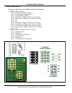
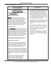
Pump Relay Note:
The style/manufacturer of the pump relay used may
change over time. To determine which terminals are
designated as the 120 VAC relay coil terminals and
which are the Common and Normally Open contact
terminals - inspect/remove the relay and refer to the
relay label or diagram.
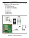
VB Field Installed Pump Note:
For field installed pumps rated up to 120 VAC 5 FLA
use on board remote pump relay connected to TB1
terminal board on the PDB (page 36). For 120 VAC
outputs between 5 and 20 FLA, use an external
relay/starter and supply 120 VAC pump power
through on-board 20 amp fuse (page 37). For
outputs above 120 VAC or 20 FLA use an external
relay/starter and feed the power through discrete
wires from a separate branch circuit. Pump power is
not passed through the on-board 20 amp fuse; use
external breaker. See output specifications for pump
on page 69.
Important Service Reminder:
When performing any troubleshooting steps outlined
in this service manual always consider the wiring
and connectors between components. Perform a
close visual inspection of all wiring and connectors
to a given component before replacement.
Failure to perform this critical step or failing to
perform this step thoroughly often results in
needless down time, unnecessary parts
replacement, and customer dissatisfaction.
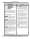
VB Models - No Factory Pump
• Check for power at the pump motor - if the
pump has power but will not start - replace/
repair pump.
• If power to the field installed pump is not present
- ensure all field installed pump controls, wiring,
connectors, and relays or starters are function-
ing correctly. Make necessary repairs to restore
power to pump.
• If field installed pump is being powered from the
the boiler follow pump power, fuse, and pump
relay steps for VW models below.
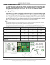
VW Models - Factory Pump Installed
• Ensure factory installed pump is running. Check
for 120 VAC at the pump motor - if the pump has
power but will not start - replace/repair pump.
• Check F2 fuse on PDB - replace fuse if blown
(page 37). Read the VB Field Installed Pump
Note to the left if this fuse is blown on a VB
model using the boiler power supply and/or
pump relay.
• With a call for heat present check for 120 VAC
at pump relay coil from MCB J2 socket pins 1 &
2 (page 29). Check MCB J2 socket/plug con-
nector pins and wiring to pump relay coil for
damage or wear - repair/replace.
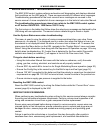
• Ensure pump relay N.O. (normally open) con-
tacts are closing with 120 VAC supplied to the
pump relay coil. If contacts do not close -
replace pump relay. See Pump Relay Note to
the left.
• Check for 120 VAC hot to the Common contact
terminal of the pump relay at TB1 terminal 1 on
the PDB (page 36). Check to ground/neutral.
• Check for 120 VAC hot return from the N. O.
contact terminal of the pump relay at TB1 termi-
nal 3 on the PDB (page 36). Check to ground/
neutral.
• Check for 120 VAC to the pump motor between
TB1 terminals 4 & 5 on the PDB (page 36).
• Ensure hot/neutral wires from pump are in good
condition and properly connected to TB1 termi-
nals 4 & 5 on the PDB (page 36).