


AOS WPC - Tech Training 41 of 72 Ashland City, TN © 2007
Servicing should only be performed by a Qualified Service Agent
VF BOILER SERVICE MANUAL
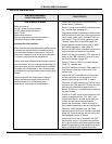
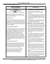
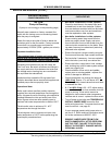
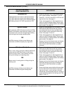
ERROR MESSAGES - TROUBLESHOOTING
The EMC 5000 control system performs exhaustive self diagnostics and displays detected
fault conditions on the UIM (page 6). There are approximately 80 different error messages.
Troubleshooting procedures for the most common error messages are covered in this
service manual. A more complete list of error messages is in the boiler’s Instruction Manual.
The troubleshooting procedures shown here relate to the EMC 5000 control system
on VF boilers VW/VB 500 - 1000 Series 100/101 only.
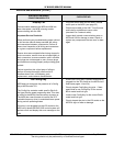
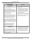
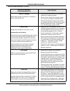
The first column in the tables that follow show the actual error message as displayed by the
UIM along with an explanation. The second column details things to check or repair.
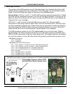
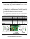
Use the System Status menu when troubleshooting:
This menu is used to view the status of various components/switches, gas valve, flame
sensors etc. An asterisk (*) is displayed next to a menu item when the status is true or on,
the asterisk is not displayed when the status of a menu item is false or off. To access this
menu press the Menu button on the UIM, navigate to the “System Status” menu and press
Select. Using the information here along with the Sequence of Operation on page 15 is very
helpful when troubleshooting. IE; if water flow is detected by the flow switch (flow switch
contacts are closed) an asterisk (*) will appear in front of the Flow menu item; *Flow.
Things to check before servicing:
• Using the Instruction Manual that came with the boiler as reference, verify the water
piping, gas line, venting, electrical, and controls are all properly installed.
• Ensure SW1 dip switch #8 is turned on for Single Modulating Burner operation (page 30).
• Ensure the Config Key is the correct key for the Btu/hr input and fuel type (page 14).
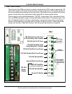
• Ensure 120 VAC is supplied to the boiler and that the polarity is correct per the electrical
requirements on page 68. 120 VAC hot wire to black, neutral to white in the junction box.
• Ensure minimum supply gas pressure is supplied to the boiler.
Resetting the EMC 5000 control:
Reset the EMC 5000 control by touching the Select button while the “Current Error” menu
screen (page 8) is displayed by the UIM.
IMORTANT SERVICE REMINDER:
When performing any troubleshooting step outlined in this service manual always consider
the wiring and connectors between components. Perform a close visual inspection of all
wiring and connectors to and from a given component before replacement.
Ensure wires were stripped before being crimped in a wire connector, ensure wires are
crimped tightly in their connectors, ensure connection pins in sockets and plugs are not
damaged or worn, ensure plugs and sockets are mating properly and providing good
contact.
Failure to perform this critical step or to perform this step thoroughly often results in
needless down time, unnecessary parts replacement, and customer dissatisfaction.