


VF BOILER SERVICE MANUAL
AOS WPC - Tech Training 48 of 72 Ashland City, TN © 2007
Servicing should only be performed by a Qualified Service Agent
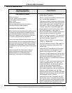
ERROR MESSAGES (CONT)
DISPLAYED MESSAGE
CONDITION/INDICATES
CHECK/REPAIR
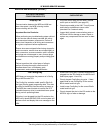
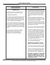
“Sequence Err”
Enable/disable circuit wires to VFD disconnected.
1-10 VDC instruction wires to VFD disconnected.
1-10 VDC instruction wires to VFD reversed polarity.
MCB failing to send 1-10 VDC instruction to VFD.
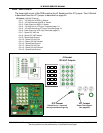
• Ensure all wiring to VFD is connected properly.
and in good condition. See pages 11 and 34.
• Check for 1-10 VDC instruction on VFD low volt-
age terminal strip. See page 11.
• Close visual inspection of J24 plug/socket con-
nection on MCB Daughter Board. Ensure plug/
socket connect is in good condition and making
good contact. See page 34.
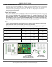
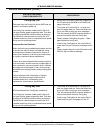
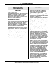
“Ignition Speed”
Wiring between MCB J24 socket and the Hall Effect
Sensor in the blower motor end cap is open or cross
connected. Fault occurred at beginning of heating
cycle during the pre purge operating state.
OR
Hall Effect sensor is failing to send blower rpm
information to MCB during the pre purge state.
• Ensure all wring between the J24 socket on the
MCB and the Hall Effect sensor are properly
connected and the red, blue, and black wires
have not been cross connected in the wiring
chase. See pages 13 and 34.
• Close visual inspection of J24 plug/socket con-
nection on MCB Daughter Board. Ensure plug/
socket connect is in good condition and making
good contact. See page 34.
• Remove end cap from blower motor and inspect
Hall Effect sensor for any sign of damage or
wear. Ensure Hall Effect sensor is properly
mounted.
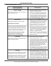
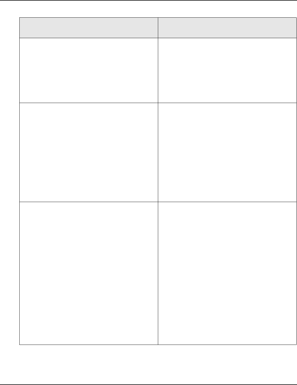
“Mtr Spd < Min Spd”
One or more wiring connections between MCB J24
socket and the Hall Effect Sensor in the blower
motor end cap is open. Fault condition occurred
during the heating cycle operating state.
OR
Blower motor is running slow or failing during the
heating cycle.
OR
Hall Effect sensor is failing to send blower rpm
information to MCB during the heating state.
• Ensure all wring between the J24 socket on the
MCB and the Hall Effect sensor are properly
connected and the red, blue, and black wires
have not been cross connected in the wiring
chase. See pages 13 and 34.
• Close visual inspection of J24 plug/socket con-
nection on MCB Daughter Board. Ensure plug/
socket connect is in good condition and making
good contact. See page 34.
• Remove end cap from blower motor and inspect
Hall Effect sensor for any sign of damage or
wear. Ensure Hall Effect sensor is properly
mounted.
• Ensure the blower motor shaft and blower wheel
are not obstructed. Ensure blower motor bear-
ings are not worn - motor cycling on thermal
overload etc. Ensure blower motor is running at
proper speed throughout the heating cycle. See
pages 11 and 13.