


AOS WPC - Tech Training 13 of 72 Ashland City, TN © 2007
Servicing should only be performed by a Qualified Service Agent
VF BOILER SERVICE MANUAL
PRINCIPLE OF OPERATION (CONT)
Blower Speed Verification - Hall Effect Sensor
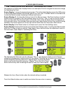
The MCB (page 25) initiates blower operation by closing the VFD enable/disable circuit AND
sending a 1-10 VDC speed instruction to the VFD (page 11) to energize the blower and to
modulate blower speed.
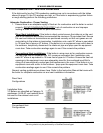
The MCB monitors actual blower speed (rpm) to verify the speed dictated by the instruction
has been achieved and to change the instruction as necessary. Actual blower speed
information is relayed to the MCB by a “Hall Effect” sensor built into the end cap of the
blower motor. Three wires connect between the J24 socket on the MCB Daughter Board
(page 34) and the Hall Effect sensor to sense blower speed. See the images below.
Example: If the MCB has sent an 4.3 VDC instruction to the VFD to run the blower at 2500
rpm and the actual rpm relayed back from the Hall Effect sensor indicates the blower is
running at 2400 rpm, the MCB will adjust (increase) the DC volt instruction slightly until the
actual rpm information matches the instruction sent by the MCB. See VFD and Blower
Speed operation on page 11.
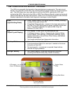
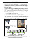
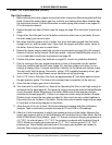
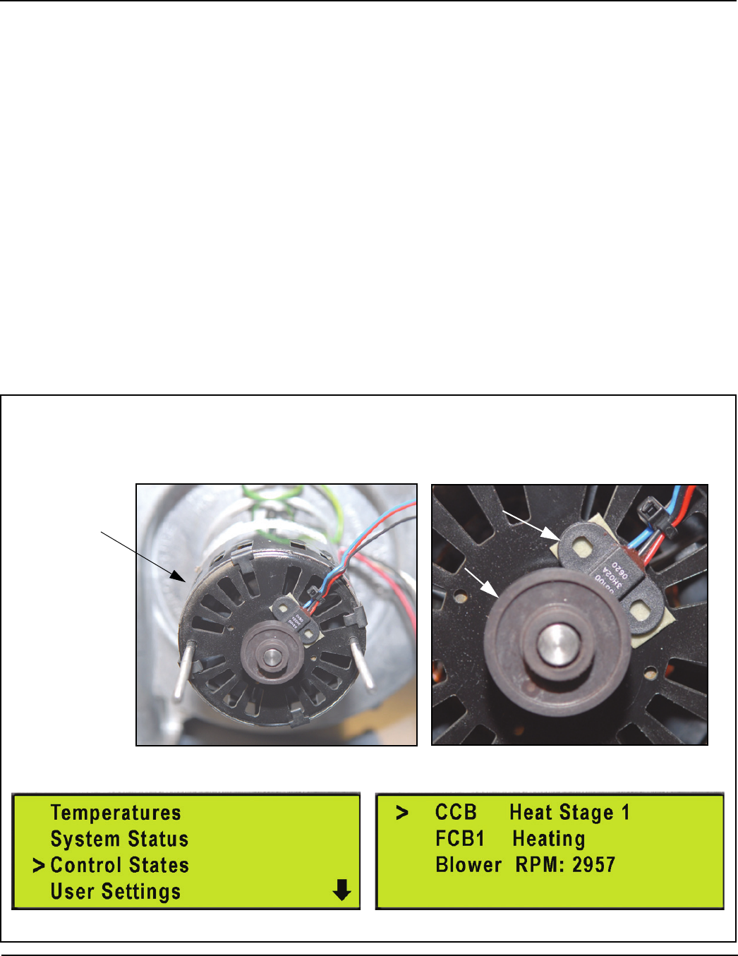
The actual blower speed can be viewed in the Control States menu in real time through the
UIM see pages 4 - 8 and 9 for instructions on how to navigate to this menu.
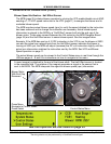
Control States Menu
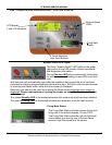
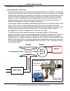
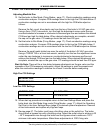
A round magnet is attached to the end of the blower shaft. The Hall Effect sensor is located
in the magnetic field. The rotation of the magnet generates a signal in the sensor that is
sent to the MCB. The MCB interprets this signal as blower speed (rpm) information.
Magnet
Hall Effect Sensor
Blower Motor
With End Cap
Removed
See the important service notes on page 34
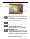
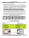
Press Menu
Navigate to Control States
Press Select