


AOS WPC - Tech Training 15 of 72 Ashland City, TN © 2007
Servicing should only be performed by a Qualified Service Agent
VF BOILER SERVICE MANUAL
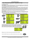
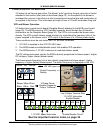
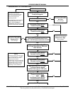
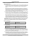
SEQUENCE OF OPERATION
MCB board applies power to pump relay
Pump Is Energized
Flow Switch Closes Contacts NO
Boiler enters Service Mode
and locks out. UIM displays
No Flow
Error message
MCB Board
Closes VFD Enable/Disable Circuit
Sends 1-10 VDC Speed Instruction to VFD
Low Blower Prover Switch
Contacts Verified Open
YES
YES
NO
EMC 5000 Control System
compares the temperature read
from controlling probe (Inlet or
remote Tank/Loop) to the
Operating Set Point.
If the temperature read is less than
the Operating Set Point minus
Stage 1 Differential AND the
Enable/Disable (thermostat) circuit
is closed a call for heat is activated
Call For Heat is Activated
High Blower Prover Switch
Contacts Verified Open
Boiler enters Service Mode
and locks out. UIM displays
Blower Prov Stg1
Error message
NO
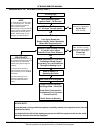
Blower Is Energized By VFD
Pre Purge State (approx 5000 rpm)
10-30 Seconds
Low Blower Prover Switch
Contacts Verified Closed
High Blower Prover Switch
Contacts Verified Closed
Boiler enters Service Mode
and locks out. UIM displays
Sequence Err
Error message
YES
YES
NO
NO
MCB Instructs VFD (1-10 VDC)
To Reduce Blower Speed
Ignition State (approx 2100 rpm)
High Blower Prover Switch
Contacts Verified Open
AND
Low Blower Prover Switch
Contacts Remain Closed
YES
YES
Next Page
NO
NOTE
The events shown in this flow chart
are in sequential order. The EMC
5000 is a multi-task control that
performs some functions
simultaneously. Only key events are
shown in order to provide a general
understanding of how the control
operates. Event timings can vary
depending on actual conditions.
NO