


VF BOILER SERVICE MANUAL
AOS WPC - Tech Training 36 of 72 Ashland City, TN © 2007
Servicing should only be performed by a Qualified Service Agent
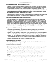
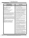
PDB - SECTION A
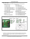
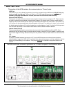
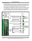
The left side of the PDB circuit board contains a terminal strip (TB1) used to connect the 120
VAC power supply to the boiler, the pump relay, and the pump motor. VW models will have a
factory mounted pump powered by the pump relay; VB models are not equipped with factory
pumps. Review the output specification table (page 69) for field supplied pumps.
Power supply must be dedicated/isolated: 120 VAC, single phase, with a grounded neutral
line, per NEMA standards using a 30 amp dedicated circuit breaker. The power supply must
be in a dedicated conduit. Hot wires, neutral wires, and ground wires must not be shared
with any other appliances including other VF boilers. External control or Tank/Loop Probe
wiring must also be in dedicated conduits. See the power requirements on page 68.
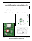
1
2
3
4
5
6
7
8
9
10
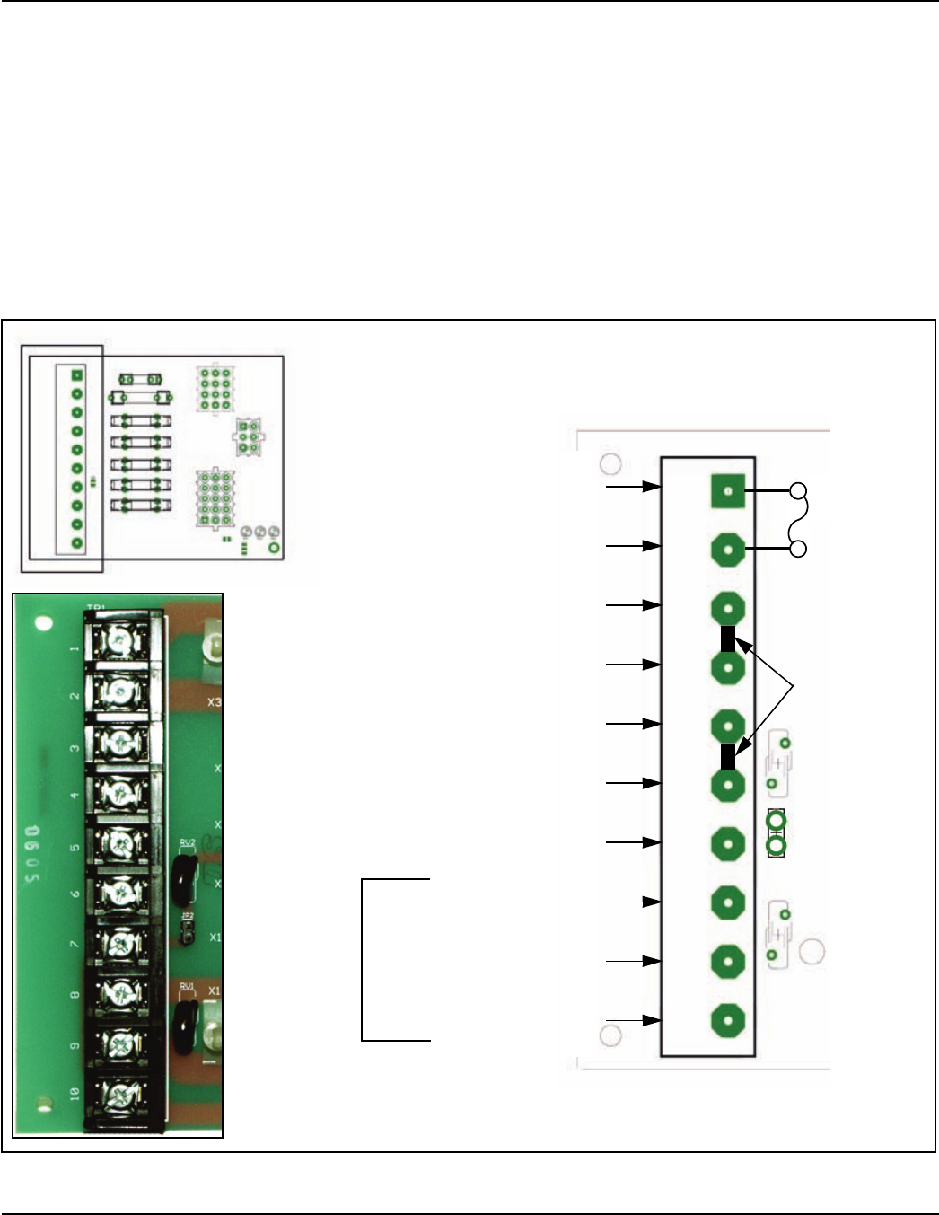
A
Ground To Boiler
JP2 Jumper
Should be on -
removed during
manufacturing
only
120 VAC Neutral Wire
120 VAC Hot Wire
(From Boiler On/Off Switch)
120 VAC
Power
Supply
Ground Wire From Pump
120 VAC Neutral Wire From Pump
120 VAC Hot Wire From Pump
120 VAC Neutral Wire
Internal
Connections
120 VAC Hot To F2 Fuse
120 VAC Hot From F2 Fuse
To Pump Relay Com Contact
F2 Fuse
20 AMP
(See page 37)
120 VAC Hot Wire From
Pump Relay N.O. Contact
TB1