


VF BOILER SERVICE MANUAL
AOS WPC - Tech Training 16 of 72 Ashland City, TN © 2007
Servicing should only be performed by a Qualified Service Agent
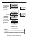
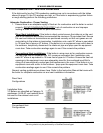
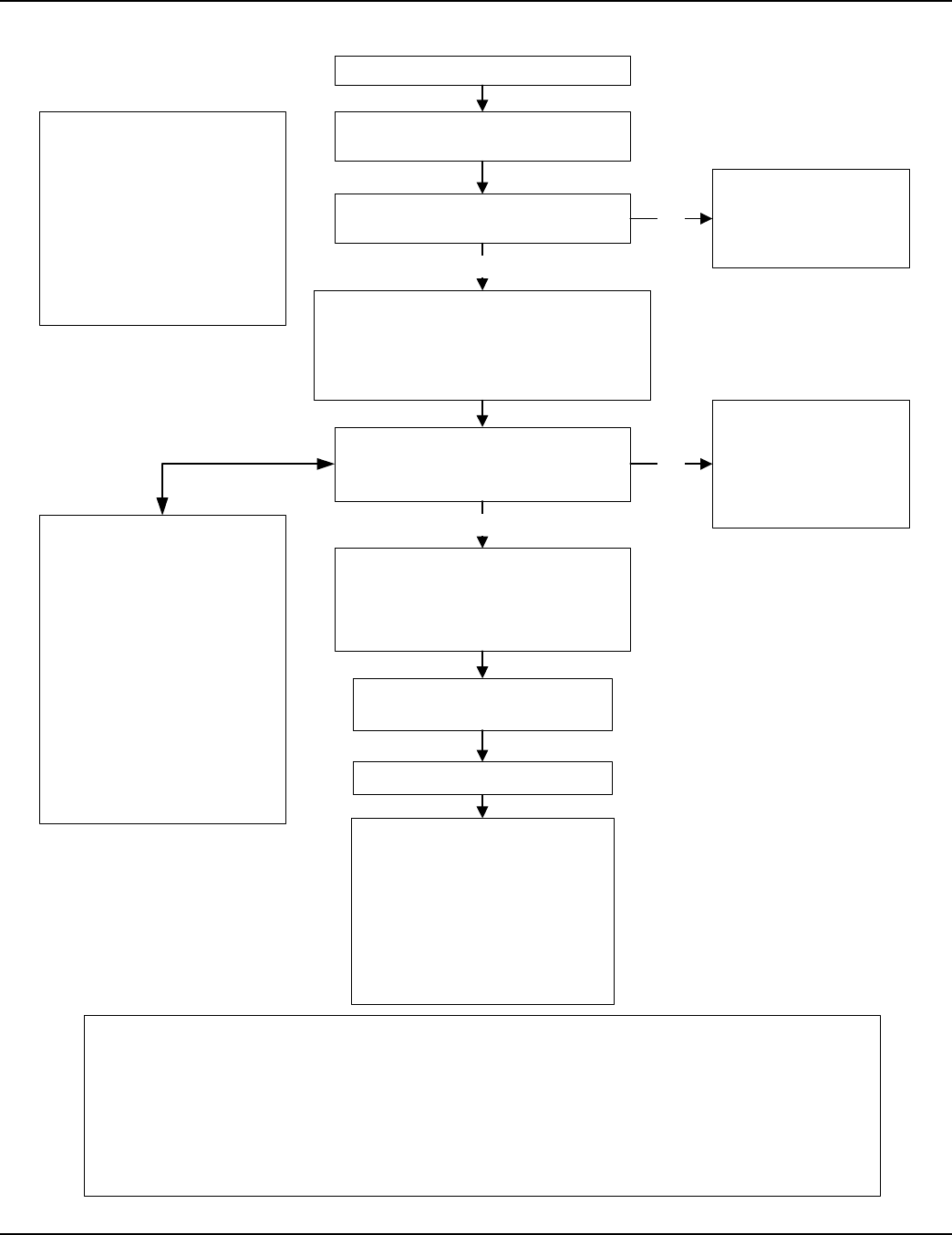
SEQUENCE OF OPERATION (CONT)
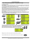
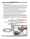
MCB Senses Minimum
2.7 AC Amps Through Ignitor
Gas Valve Is Energized
Fuel Gas Is Drawn Into
Blower Inlet By Venturi Assembly
Mixed With Combustion Air
Boiler enters Service Mode
and locks out. UIM displays
Igniter Stg1
Error message
Minimum Flame Sensing Current
2.5 µA (DC micro amps)
Detected From Flame Sensors
Water Is Heated To
Operating Set Point
Blower Runs 25 Seconds
Post Purge State – Shuts Off.
Pump Runs Continuous Or
Programmed Post Circulate
Period Shuts Off.
Boiler Goes Into Standby
MCB Energizes Ignitor
Ignition State – 18 Seconds
Previous Page
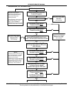
NOTE
The events shown in this flow chart
are in sequential order. The EMC
5000 is a multi-task control that
performs some functions
simultaneously. Only key events are
shown in order to provide a general
understanding of how the control
operates. Event timings can vary
depending on actual conditions.
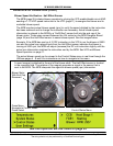
SERVICE NOTE
VF boilers utilize two flame sensors.
One is positioned closer to the buner
than the second to enable flame
detection during low and high fire
conditions.
The wiring from the two flame
sensors is joined and connects to a
single connection point on the MCB
circuit board.
When the “Flame Stg1” error
message is displayed remove,
inspect, and clean both flame
sensors.
YES
NO
SERVICE NOTE:
In standby and running modes the system constantly monitors the signals and the internal
operation for faults.
Any detected fault will halt the heating sequence and shift the system to the service mode
where the detected fault will be displayed.
After 1 or 3 trials
(SW1 dip switch 2 setting)
Control enters Service Mode
and locks out. UIM displays
Flame Stg1
Error message
NO
Gas Valve Is De-Energized
MCB Instructs VFD (1-10 VDC)
To Modulate Blower Speed
According To Load Conditions
Throughout Heating Cycle
YES