


Setup Menu Teledyne API T801 NDIR CO2 Analyzer Operation Manual
84
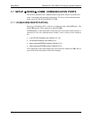
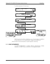
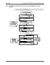
5.9.2. ANALOG OUTPUT
The T801 analyzer comes equipped with four analog outputs.
The first two analog output (A1 & A2) signals represent the currently
measured CO
2
concentration (see Section 5.4.2).
The third analog output (A3) is not used.
The fourth output (A4) outputs a signal that can be set to represent the
current value of one of several test functions (see Table 5-8).
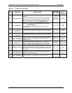
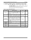
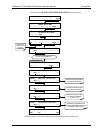
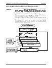
5.9.3. ANALOG I/O CONFIGURATION
The following lists the analog I/O functions that are available in the T801
analyzer.
Table 5-4: DIAG - Analog I/O Functions
SUB MENU FUNCTION
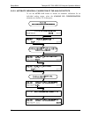
AOUT
CALIBRATED
Initiates a calibration of the A1, A2, A3 and A4 analog output channels that determines the
slope and offset inherent in the circuitry of each output.
These values are stored in the memory and applied to the output signals by the CPU
automatically.
CONC_OUT_1
Sets the basic electronic configuration of the A1 output (CO
2
Concentration).
There are four options:
RANGE
1
: Selects the signal type (voltage or current loop) and level of the output
REC OFS: Allows them input of a DC offset to let the user manually adjust the output
level
AUTO CAL: Enables / Disables the AOUT CALIBRATION Feature
CALIBRATED: Performs the same calibration as AOUT CALIBRATED, but on this one
channel only.
CONC_OUT_2
Same as for CONC_OUT_1 but for analog channel A2 and only if Auto or Dual range is
selected (CO
2
high range, RNG2)
Not used.
TEST OUTPUT
Same as for CONC_OUT_1 but for analog channel A4 (TEST CHANNEL)
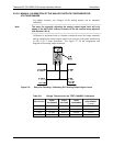
AIN
CALIBRATED
Initiates a calibration of the A-to-D Converter circuit located on the Motherboard.
XIN1
.
.
.
XIN8
For each of 8 external analog inputs channels, shows the gain, offset, engineering
units, and whether the channel is to show up as a Test function.
1
Any changes made to RANGE or REC_OFS require recalibration of this output.
07274B DCN6418