


Getting Started Teledyne API T801 NDIR CO2 Analyzer Operation Manual
52
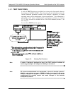
MESSAGE DEFINITION
SAMPLE PRESS WARN
Sample gas pressure outside of operational parameters.
SYSTEM RESET
1
The analyzer was rebooted or the CPU was reset.
1
Does not clear after power up.
2
Clears the next time successful span calibration is performed.
3
Clears the next time successful zero calibration is performed.
4
Only active if the Concentration Alarm Option is installed
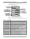
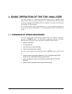
3.4.2. FUNCTIONAL CHECKS
After the analyzer’s components have warmed up for at least 60 minutes, verify
that the software properly supports any hardware options that were installed. For
information on navigating through the analyzer’s software menus, see the menu
trees described in Appendix A.1.
Check to make sure that the analyzer is functioning within allowable operating
parameters. Appendix C includes a list of test functions, viewable from the
analyzer’s front panel, and their expected values. These functions are also useful
tools for diagnosing performance problems (Section 11.1.2) with your analyzer.
The enclosed Final Test and Validation Data Sheet (PN 068340
000) lists these
values before the instrument left the factory. To view the current values of these
parameters, press the front panel button sequence for TEST functions. Remember
until the unit has completed its warm up these parameters may not have
stabilized.
If your local area network (LAN) is running a dynamic host configuration
protocol (DHCP) software package, the Ethernet will automatically configure its
interface with your LAN. However, it is a good idea to check these settings to
make sure that the DHCP has successfully downloaded the appropriate network
settings from your network server (see Section 6.3.1).
If yo
ur network is not running DHCP, see your network administrator or
configure the Ethernet interface manually (see Section 6.3.2).
3.4.3. INITIAL CALIBRATION
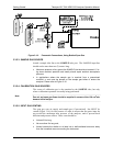
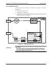
To perform the calibration you must have sources for zero air and span gas
available for input into the SAMPLE port on the back of the analyzer. See
Section 3.3.2.1 for instructions for connecting these gas sources.
The initial calibration should be carried out
using the same reporting range set up
as used during the analyzer’s factory calibration. This will allow you to compare
your calibration results to the factory calibration as listed on the Final Test and
Validation Data Sheet.
If both available DAS parameters for a specific gas type are being reported via
the instrument’s analog outputs e.g. CONC1 and CONC2 when the DUAL
range mode is activated, separate calibrations should be carried out for each
parameter.
07274B DCN6418