


Teledyne API T801 NDIR CO2 Analyzer Operation Manual Principles of Operation
213
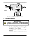
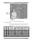
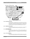
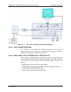
D5 (Yellow) –CO2 Sensor Heater
D1 (RED)
Watchdog Indicator
Figure 12-9: Status LED Locations – Relay PCA
12.5.3.2. WATCHDOG CIRCUITRY
The most important of the status LEDs on the relay board is the red I
2
C Bus
watch-dog LED. It is controlled directly by the analyzer’s CPU over the I
2
C Bus.
Special circuitry on the relay PCA watches the status of D1. Should this LED
ever stay ON or OFF for 30 seconds, indicating that the CPU or I
2
C bus has
stopped functioning, this Watchdog Circuit automatically shuts off all heaters.
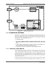
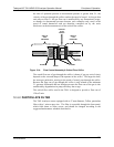
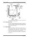
12.5.3.3. TEMPERATURE CONTROL
A cartridge heater implanted into the sensor is the heat source. The temperature
of the sensor is measured by a thermistor also inserted into the sensor body.
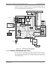
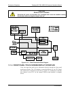
12.5.4. MOTHERBOARD
This printed circuit assembly provides a multitude of functions including, A/D
conversion, digital input/output, PC-104 to I
2
C translation, temperature sensor
signal processing, and serves as a pass-through for the RS-232 and RS-485
signals.
12.5.4.1. A TO D CONVERSION
Analog signals, such as the voltages received from the analyzer’s various sensors,
are converted into digital signals that the CPU can understand and manipulate by
07274B DCN6418