


Teledyne API T801 NDIR CO2 Analyzer Operation Manual Getting Started
33
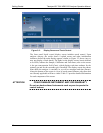
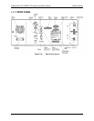
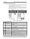
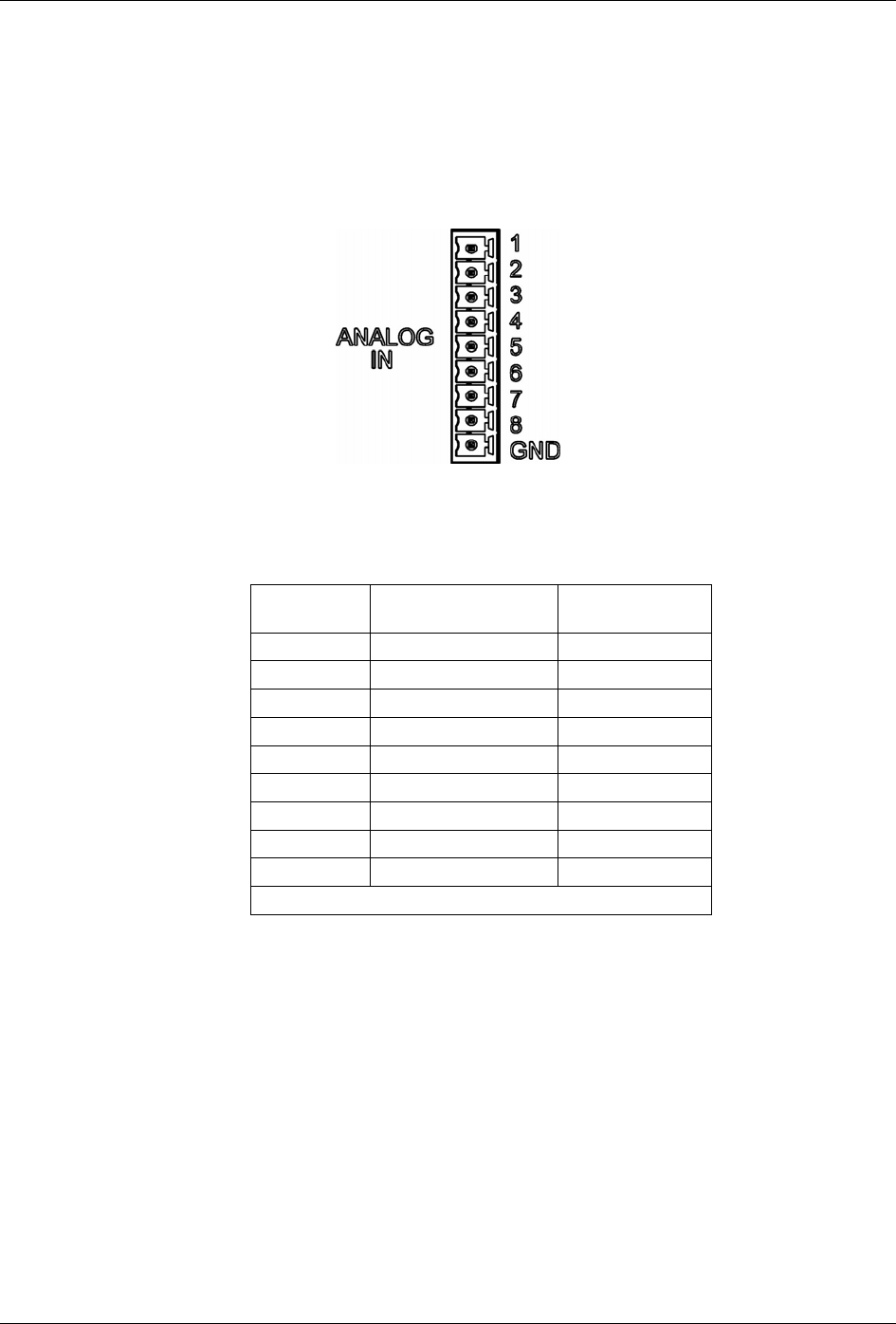
3.3.1.2. CONNECTING ANALOG INPUTS (OPTION 64)
The Analog In connector is used for connecting external voltage signals from
other instrumentation (such as meteorological instruments) and for logging these
signals in the analyzer’s internal DAS. The input voltage range for each analog
input is 0-10 VDC, and the input impedance is nominally 20kΩ in parallel with
0.1µF.
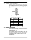
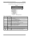
Figure 3-6. Analog In Connector
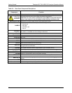
Pin assignments for the Analog In connector are presented in Table 3-4.
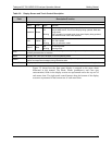
Table 3-4: Analog Input Pin Assignments
PIN DESCRIPTION
DAS
PARAMETER
1
1 Analog input # 1 AIN 1
2 Analog input # 2 AIN 2
3 Analog input # 3 AIN 3
4 Analog input # 4 AIN 4
5 Analog input # 5 AIN 5
6 Analog input # 6 AIN 6
7 Analog input # 7 AIN 7
8 Analog input # 8 AIN 8
GND Analog input Ground N/A
1
See Section 7 for details on setting up the DAS.
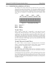
3.3.1.3. CONNECTING ANALOG OUTPUTS
The T801 is equipped with several analog output channels accessible through the
ANALOG OUT connector on the rear panel of the instrument. The standard
configuration for these outputs is VDC. An optional current loop output is
available for each (Section 3.3.1.4).
When the instrument is in its default configuration, channel A1 ou
tputs a signal
that is proportional to the CO
2
concentration of the sample gas. If Dual or Auto
range is configured, channels A1 and A2 each output a signal proportional to the
CO
2
concentration of the sample gas. Please refer to Section 5.4.3 for details.
Channel A3 is not used.
07274B DCN6418