


Getting Started Teledyne API T801 NDIR CO2 Analyzer Operation Manual
38
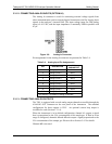
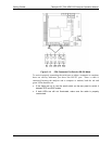
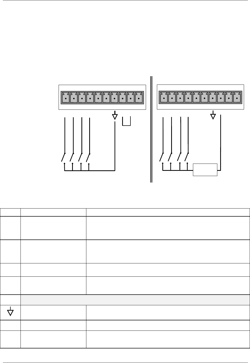
3.3.1.6. CONNECTING THE CONTROL INPUTS
If you wish to use the analyzer to remotely activate the zero and span calibration
modes, several digital control inputs are provided through a 10-pin connector
labeled CONTROL IN on the analyzer’s rear panel.
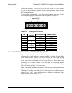
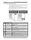
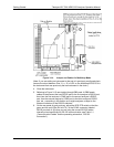
There are two methods for energizing the control inputs. The internal +5V
available from the pin labeled “+” is the most convenient method (Figure 3-10,
left). However, if full isolation is required, an external 5 VDC power supply
should
be used (Figure 3-10, right).
CONTROL IN
A B C D E F U
+
SPAN/ZERO CAL
CAL/SMPL MODE
CONTROL IN
A B C D E F U
+
-
+
5 VDC
Power Supply
Local Power Connections
External Power Connections
RANGE SELECTION
CO2 CAL
SPAN/ZERO CAL
CAL/SMPL MODE
RANGE SELECTION
CO2 CAL
Figure 3-10: Control Input Connector
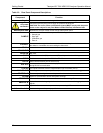
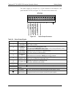
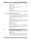
Table 3-7: Control Input Signals
Input # Status Definition
Open/Closed Condition Description
A
CALIBRATION MODE or
SAMPLE MODE
Closed: initiates Calibration mode. Front panel display Mode field will read
CAL CO2 R or CAL CO2 ZR.
Open: initiates Sample (Measure) mode. Front panel display Mode field will
read SAMPLE.
B
REMOTE SPAN or REMOTE
ZERO CALIBRATION
Closed: initiates remote SPAN calibration mode as part of performing a low
span calibration. Front panel display Mode field will read CAL CO2 SR.
Open: initiates remote ZERO calibration mode. Front panel display Mode
field will read ZERO MODE.
C
RANGE2 or RANGE1
CALIBRATION
Closed: selects High Range for calibration (C2H).
Open: selects Low Range (C2L), default range in single range mode.
D
CO
2
SENSOR
CALIBRATION
Closed: Initiates CO
2
sensor calibration. Front panel display Mode field will
read CAL CO2 R or CAL CO2 ZR.
Open: Exits CO
2
sensor calibration and returns to SAMPLE mode.
E & F
SPARE
Digital Ground
The ground level from the analyzer’s internal DC power supplies (same as
chassis ground)
U
External Power input
Input pin for +5 VDC required to activate Pins A – F.
+
5 VDC output
Internally generated 5V DC power. To activate inputs A – F, place a jumper
between this pin and the “U” pin. The maximum amperage through this port
is 300 mA (combined with the analog output supply, if used).
07274B DCN6418