


Basic Operation of the T801 Analyzer Teledyne API T801 NDIR CO2 Analyzer Operation Manual
60
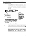
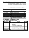
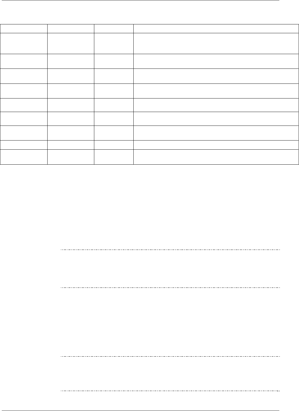
Table 4-2: Test Functions Defined
PARAMETER DISPLAY TITLE UNITS DEFINITION
Range
RNG
RN1
RN2
%
The full scale limit at which the reporting range of the analyzer is
currently set. THIS IS NOT the Physical Range of the instrument.
See Section 5.4.1 for more information.
Stability
STABIL
%
Standard deviation of CO
2
concentration readings. Data points are
recorded every ten seconds using the last 25 data points.
Sample Pressure
PRES
In-Hg-A
The absolute pressure of the Sample gas as measured by a
pressure sensor located inside the sample chamber.
Sample Flow
SAMP FL
cm
3
/min
Sample mass flow rate as measured by the flow rate sensor in the
sample gas stream.
CO
2
Sensor
Slope
CO2 SLOPE
- CO
2
slope, computed during zero/span calibration.
CO
2
Sensor
Offset
CO2 OFST
- CO
2
offset, computed during zero/span calibration.
CO
2
Cell
Temperature
CO2 CELL
TEMP
C
The current temperature of the CO
2
sensor measurement cell.
Box Temperature
BOX TEMP
C
The temperature inside the analyzer chassis.
Current Time
TIME
-
The current time. This is used to create a time stamp on DAS
readings, and by the AUTOCAL feature to trigger calibration events.
4.3. CALIBRATION MODE
The T801 will switch into calibration mode when the user presses the CAL
button. In this mode the user can, in conjunction with introducing zero or span
gases of known concentrations into the analyzer, cause it to adjust and recalculate
the slope (gain) and offset of the its measurement range. This mode is also used
to check the current calibration status of the instrument.
Section 9 provides more information about setting up and perform
ing standard
calibration operations or checks.
Note
It is recommended that span calibration be performed at 80% of full scale of
the analyzer’s currently selected reporting range.
EXAMPLE: If the reporting range is set for 0 to 10%, an appropriate span
point would be 8%.
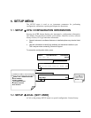
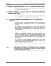
4.4. SETUP MODE
The SETUP mode is used to configure the analyzer’s hardware and software
features, perform diagnostic procedures, gather information on the instrument’s
performance and configure or access data from the internal data acquisition
system (DAS) (Section 7). SETUP Mode has a Primary and a Secondary setup
menu.
Note
Any changes made to a variable during one of the SETUP procedures are not
acknowledged by the instrument until the ENTR button is pressed. If the EXIT
button is pressed before the ENTR button, the analyzer will beep to notify the
user that the newly entered value has been lost.
07274B DCN6418