


Teledyne API T801 NDIR CO2 Analyzer Operation Manual Table of Contents
xiii
Figure 5-4: Alternative Setup Using 250Ω Resistor for Checking Current Output Signal Levels..... 95
Figure 7-1: Default DAS Channel Setup......................................................................................... 133
Figure 7-2: APICOM Remote Control Program Interface............................................................... 148
Figure 7-3: APICOM User Interface for Configuring the DAS ........................................................149
Figure 7-4: DAS Configuration Through a Terminal Emulation Program....................................... 150
Figure 9-1: Pneumatic Connections Using Bottled Span Gas........................................................162
Figure 10-1: Sample Particulate Filter Assembly..............................................................................176
Figure 11-1: Viewing and Clearing Warning Messages ...................................................................182
Figure 11-2: Example of Signal I/O Function.................................................................................... 185
Figure 11-3: CPU Status Indicator....................................................................................................186
Figure 11-4: Relay PCA Status LEDS Used for Troubleshooting..................................................... 187
Figure 11-5: T801 – Internal Gas Flow............................................................................................. 188
Figure 11-6: Location of Diagnostic LEDs on CO
2
Sensor PCA.......................................................199
Figure 11-7: Critical Flow Restrictor Assembly / Disassembly ......................................................... 200
Figure 12-1. CO
2
Sensor Theory of Operation ................................................................................. 204
Figure 12-2. CO
2
Sensor PCA Layout and Electronic Connections................................................. 205
Figure 12-3: Internal Pneumatic Flow............................................................................................... 206
Figure 12-4: Flow Control Assembly & Critical Flow Orifice............................................................. 207
Figure 12-5: T801 Electronic Block Diagram.................................................................................... 209
Figure 12-6. CPU Card ..................................................................................................................... 210
Figure 12-7: Relay PCA Layout (PN 04135)..................................................................................... 211
Figure 12-8: Relay PCA with AC Relay Retainer in Place................................................................212
Figure 12-9: Status LED Locations – Relay PCA .............................................................................213
Figure 12-10: Power Distribution Block Diagram................................................................................216
Figure 12-11: Front Panel and Display Interface Block Diagram .......................................................217
Figure 12-12: Basic Software Operation............................................................................................. 218
Figure 13-1: Triboelectric Charging ..................................................................................................221
Figure 13-2: Basic anti-ESD Workbench.......................................................................................... 224
LIST OF TABLES
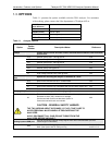
Table 1-1. Analyzer Options ............................................................................................................18
Table 2-1: T801 CO
2
Specifications ................................................................................................21
Table 3-1: Ventilation Clearance ..................................................................................................... 24
Table 3-2: Display Screen and Touch Control Description ............................................................. 27
Table 3-3: Rear Panel Component Descriptions............................................................................. 30
Table 3-4: Analog Input Pin Assignments .......................................................................................33
Table 3-5: Analog Output Pin-Outs .................................................................................................34
Table 3-6: Status Output Signals..................................................................................................... 37
Table 3-7: Control Input Signals...................................................................................................... 38
Table 3-8: Front Panel Display during System Warm-Up ...............................................................50
Table 4-1: Analyzer Operating Modes.............................................................................................58
Table 4-2: Test Functions Defined .................................................................................................. 60
Table 4-3: Primary Setup Mode Features and Functions................................................................ 61
Table 4-4: Secondary Setup Mode Features and Functions........................................................... 61
Table 5-1: Password Levels ............................................................................................................72
Table 5-2: Variable Names (VARS).................................................................................................79
Table 5-3: Diagnostic Mode (DIAG) Functions................................................................................81
Table 5-4: DIAG - Analog I/O Functions.......................................................................................... 84
Table 5-5: Analog Output Voltage Range Min/Max.........................................................................86
Table 5-6: Voltage Tolerances for the TEST CHANNEL Calibration .............................................. 91
Table 5-7: Current Loop Output Check ...........................................................................................95
Table 5-8: Test Channels Functions available on the T801’s Analog Output ................................. 98
07274B DCN6418