


Teledyne API T801 NDIR CO2 Analyzer Operation Manual Basic Operation of the T801 Analyzer
61
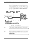
Setup Mode can be protected by password security through the SETUP>PASS
menu (Section 5.5) to prevent unauthorized or inadvertent configuration
adjustm
ents.
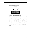
4.4.1. PRIMARY SETUP MENU
For a visual representation of the software menu trees, refer to Appendix A-1.
The areas accessible under the SETUP mode are shown below:
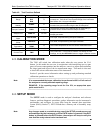
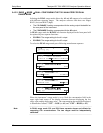
Table 4-3: Primary Setup Mode Features and Functions
MODE OR FEATURE
MENU
ITEM
DESCRIPTION
MANUAL
SECTION
Analyzer Configuration
CFG
Lists key hardware and software configuration information 5.1
Auto Cal Feature
ACAL
(Special configuration; consult factory). n/a
Internal Data Acquisition
(DAS)
DAS
Used to set up the DAS system and view recorded data 7
Analog Output Reporting
Range Configuration
RNGE
Used to configure the output signals generated by the
instruments Analog outputs.
5.4
Calibration Password
Security
PASS
Turns the calibration password feature ON/OFF 5.2
Internal Clock Configuration
CLK
Used to Set or adjust the instrument’s internal clock 5.6
Advanced SETUP features
MORE
This button accesses the instrument’s secondary setup
menu
See
Table 6-5
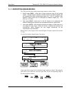
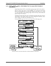
4.4.2. SECONDARY SETUP MENU (SETUP>MORE)
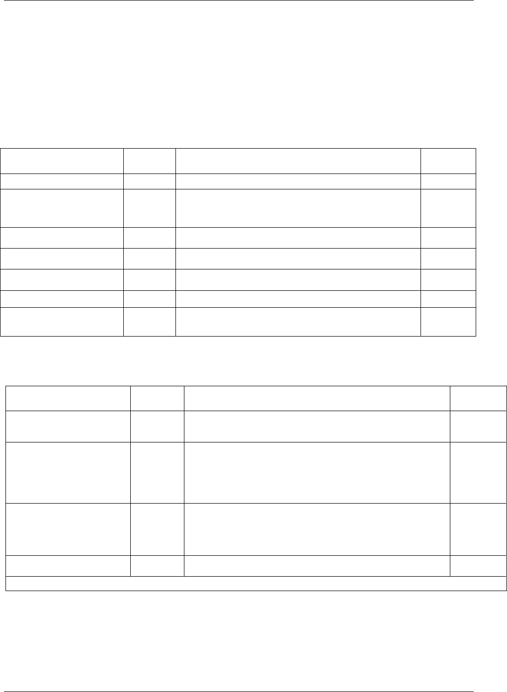
Table 4-4: Secondary Setup Mode Features and Functions
MODE OR FEATURE
MENU
ITEM
DESCRIPTION
MANUAL
SECTION
External Communication
Channel Configuration
COM
Used to set up and operate the analyzer’s various external I/O
channels including RS-232, RS-485, modem communication
and/or Ethernet access.
5.7
System Status Variables
VARS
Used to view various variables related to the instruments current
operational status
Changes made to any variable will not be recorded in the
instrument’s memory until the ENTR key is pressed.
Pressing the EXIT key ignores the new setting.
5.8
System Diagnostic Features
and
Analog Output Configuration
DIAG
Used to access a variety of functions that configure, test or
diagnose problems with a variety of the analyzer’s basic
systems.
Most notably, the menus to configure the output signals
generated by the instruments Analog outputs are located here.
5.9
Alarm Limit Configuration
1
ALRM
Used to turn the instrument’s two alarms on and off as well as
set the trigger limits for each.
5.10
1
Alarm warnings only present when optional concentration alarm relay package is installed.
07274B DCN6418