


Getting Started Teledyne API T801 NDIR CO2 Analyzer Operation Manual
34
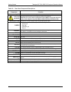
Channel A4 is special. It can be set by the user (see Section 5.9.3.10) to output
any one of the parameters accessible through the <TST TST> buttons of the
unit’s front panel menu.
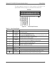
To access these signals attach a strip chart recorder and/or data-logger to the
appropriate analog output connections on the rear panel of the analyzer.
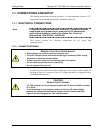
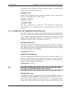
A
NALOG OUT
A1
A
2 A3 A4
+ - + - + - + -
Figure 3-7: Analog Output Connector
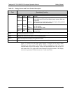
Table 3-5: Analog Output Pin-Outs
PIN
ANALOG
OUTPUT
VOLTAGE SIGNAL CURRENT SIGNAL
1 V Out I Out +
2
A1
Ground I Out -
3 V Out I Out +
4
A2
Ground I Out -
5 V Out I Out +
6
A3
(not used)
Ground I Out -
7 V Out NA
8
A4
Ground NA
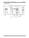
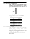
3.3.1.4. CURRENT LOOP ANALOG OUTPUTS (OPTION 41) SETUP
If your analyzer had this option installed at the factory, there are no further
connectons to be made. Otherwise, it can be installed as a retrofit for each of the
analog outputs of the analyzer . This option converts the DC voltage analog
output to a current signal with 0-20 mA output current. The outputs can be scaled
to any set of limits within that 0-20 mA range. However, most current loop
applications call for either 2-20 mA or 4-20 mA range. All current loop outputs
have a +5% over-range. Ranges with the lower limit set to more than 1 mA (e.g.,
2-20 or 4-20 mA) also have a -5% under-range.
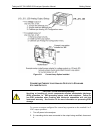
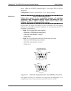
Figure 3-8 provides installation instructions and illustrates a sample combination
of one current output a
nd two voltage outputs
configuration. The section
following this provides instructions for converting current loop analog outputs to
standard 0-to-5 VDC outputs. Information on calibrating or adjusting these
outputs can be found in Section 5.9.3.7.
07274B DCN6418