


Getting Started Teledyne API T801 NDIR CO2 Analyzer Operation Manual
40
The software for this instrument is flexible enough to allow you to configure the
alarms so that you can have 2 alarm levels.
CO
2
Alarm 1 = 5%
CO
2
Alarm 2 = 10 %
Another likely configuration for this would be to disable “Alarm 1” relay and set
the other concentration on the “Alarm 2” relay.
CO
2
Alarm 1 = Disabled
CO
2
Alarm 2 = 10%
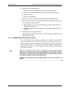
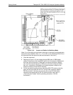
“ALARM 4” RELAY
This relay is connected to the “range bit”. If the instrument is configured for
“Auto Range” and the instrument goes up into the high range, it will turn this
relay on.
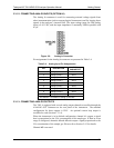
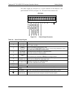
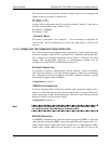
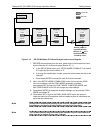
3.3.1.8. CONNECTING THE COMMUNICATIONS INTERFACES
The T-Series analyzers are equipped with connectors for remote communications
interfaces: Ethernet, USB, RS-232, optional RS-232 Multidrop, and optional RS-
485. In addition to using the appropriate cables (Table 1-1 describes the cable
options, 60A
through 60D), each type of communication m
ethod must be
configured using the SETUP>COMM menu (Section 5.7).
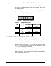
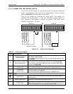
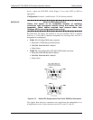
ETHERNET CONNECTION
For network or Internet communication with the analyzer, connect an Ethernet
cable from the analyzer’s rear panel Ethernet interface connector to an Ethernet
port. Although the analyzer is shipped with DHCP enabled by default, it should
be manually assigned a static IP address.
Configuration: Section 6.3
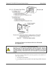
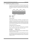
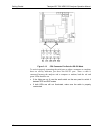
USB OPTION CONNECTION
For direct communication between the analyzer and a personal computer (PC),
connect a USB cable between the analyzer and desktop or laptop USB ports.
Setup instructions include downloading the USB driver and ensuring that the
baud rate of the PC and the analyzer match.
Configuration: Section 6.4.
Note If this option is installe
d, the rear panel COM2 port cannot be used
for anything other than Multidrop communication.
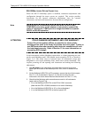
RS-232 CONNECTION
For RS-232 communications with data terminal equipment (DTE) or with data
communication equipment (DCE) connect the applicable cable option (Table 1-1:
either a DB9-fe
male-to-DB25-male cable, Option 60A, or a DB9-female-to-DB9-
female cable, Option 60B) from the analyzer’s rear panel RS-232 port to the
07274B DCN6418