


Teledyne API T801 NDIR CO2 Analyzer Operation Manual Getting Started
37
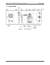
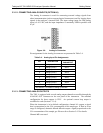
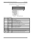
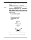
The status outputs are accessed via a 12-pin connector on the analyzer’s rear
panel labeled STATUS (see Figure 3-4). Pin-outs for this connector are:
STATUS
1 2 3 4 5 6 7 8 D
+
SYSTEM OK
CONC VALID
CAL MODE / MEAS MODE
SPAN CAL / ZERO MODE
CAL MODE – RANGE 2
Figure 3-9: Status Output Connector
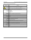
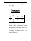
Table 3-6: Status Output Signals
Rear Panel Label Status Definition Condition
1
SYSTEM
OK/ALARM
ON if no faults are present.
OFF if alarm condition
2
CONC
VALID/CONC
INVALID
ON if concentration measurement is valid.
OFF any time the HOLD OFF feature is active, such as during calibration or when
any faults exist invalidating the measurement.
3
CAL MODE/
MEAS MODE
ON whenever the instrument is in Calibration Mode
OFF when instrument in Measure Mode
4
SPAN/ZERO
CAL
ON whenever the instrument’s SPAN point is being calibrated.
OFF whenever the instrument’s ZERO point is being calibrated.
5
RANGE2 CAL
RANGE1 CAL
ON if unit is in high range of either the DUAL or AUTO range modes.
OFF if unit is in default low, single range mode
6
CO
2
Sensor CAL
ON when CO
2
sensor is in calibration mode.
OFF when calibration mode is exited.
7 & 8
SPARE
D
EMITTER BUS The emitters of the transistors on Pins 1-8 are bussed together.
SPARE
+
DC POWER + 5 VDC, 300 mA source (combined rating with Control Output, if used).
Digital Ground The ground level from the analyzer’s internal DC power supplies
07274B DCN6418