


Troubleshooting and Service Teledyne API T801 NDIR CO2 Analyzer Operation Manual
180
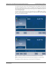
1. Note any WARNING MESSAGES and take corrective action as necessary.
2. Examine the values of all TEST functions and compare them to factory
values. Note any major deviations from the factory values and take
corrective action.
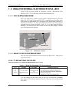
3. Use the internal electronic status LEDs to determine whether the electronic
communication channels are operating properly.
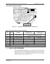
4. Verify that the DC power supplies are operating properly by checking the
voltage test points on the relay PCA.
Note that the analyzer’s DC power wiring is color-coded and these colors
match the color of the corresponding test points on the relay PCA.
5. SUSPECT A LEAK FIRST!
Technical Support data indicate that the majority of all problems are
eventually traced to leaks in the internal pneumatics of the analyzer or the
diluent gas and source gases delivery systems.
Check for gas flow problems such as clogged or blocked internal/external gas
lines, damaged seals, punctured gas lines, a damaged / malfunctioning
pumps, etc.
6. Follow the procedures defined in Section 11.6 to confirm that the analyzer’s
vital functions are wo
rking (power suppli
es, CPU, relay PCA, keyboard, etc.).
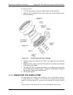
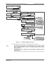
See Figure 3-5 for the general layout of components and sub-assemblies in
the analyzer.
See the wiring interconnect diagram and interconnect list in Appendix D.
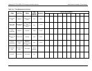
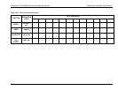
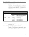
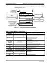
11.1.1. FAULT DIAGNOSIS WITH WARNING MESSAGES
The most common and/or serious instrument failures will result in a warning
message being displayed on the front panel. Table 11-1 lists warning messages,
along with th
eir meaning and recommended corrective action.
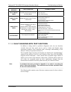
It should be noted that if more than two or three warning messages occur at the
same time, it is often an indication that some fundamental analyzer sub-system
(power supply, relay board, motherboard) has failed rather than indication of the
of the specific failures referenced by the warnings. In this case, it is
recommended that proper operation of power supplies (See Section 11.6.2), the
relay board (
See Section 11.6.6), and the A/D Board (See Section 11.6.9.1) be
confirmed before addressing the specific warning me
ssages.
07274B DCN6418