


Configuration
3-28
9124-A2-LB20-00
March 2000
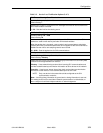
Configuring the User Data Port
Select Physical from the Data Ports menu to configure the physical
characteristics for the user data port (see Table 3-5).
Main Menu →Configuration →Data Ports →Physical
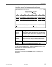
Table 3-5. Data Port Physical Interface Options (1 of 2)
Transmit Clock Source
Possible Settings: Internal, External
Default Setting: Internal
Determines whether the DTE’s transmitted data is clocked into the FrameSaver unit by
its internal transmit clock or by the external clock provided by the DTE.
NOTE: Changing settings for this configuration option causes the FrameSaver unit
to abort any physical port tests, including any DTE-initiated loopback tests.
Internal – The FrameSaver unit uses the interchange circuit DB (ITU 114) – Transmit
Signal Element Timing (TXC) (DCE source) for timing the incoming data.
External – The DTE provides the clock for the transmitted data, and the FrameSaver
unit uses the interchange circuit DA (ITU 113) – Transmit Signal Element Timing (XTXC)
(DTE source) for timing the incoming data.
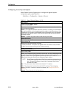
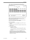
Invert Transmit Clock
Possible Settings: Auto, Enable, Disable
Default Setting: Auto
Determines whether the clock supplied by the FrameSaver unit on interchange circuit
DB (ITU 114) – Transmit Signal Element Timing (DCE Source) TXC is phase inverted
with respect to the clock used to time the incoming Transmitted Data (TD).
Auto – The port will check the clock supplied by the DCE on TXC on this port. If
necessary, the port will automatically phase invert the clock with respect to the
transmitted data.
Enable – Phase inverts the TXC clock. Use this setting when long cable lengths
between the FrameSaver unit and the DTE are causing data errors.
Disable – Does not phase invert the TXC clock.
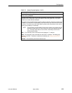
Monitor DTR
Possible Settings: Enable, Disable
Default Setting: Enable
Specifies whether the state of the DTE Ready (DTR) circuit on the user data port will be
used to determine when valid data communication is possible with the DTE. When the
DTR off condition is detected, an alarm is generated, LMI is declared down, and no
further transfer of frame relay data can occur on this interface.
Enable – Interchange circuit CD (ITU 108/1/2) – DTR is monitored to determine when
valid data is sent from the DTE.
Disable – DTR is not monitored. DTR is assumed to be asserted and data is being
transmitted, regardless of the state of the lead.