Connectors, Cables, and Pin Assignments
C-9
9124-A2-LB20-00
March 2000
DSX-1 Connector
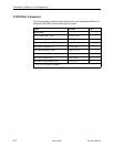
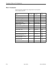
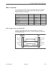
If your model includes a DSX-1 interface, the following table shows the signals
and pin assignments for the 8-position modular DSX-1 interface. The DSX-1
Adapter is required for this interface.
Function
Circuit Direction Pin Number
Receive Ring R1 From DTE 1
Receive Tip T1 From DTE 2
Shield — — 3
Transmit Ring R To DTE 4
Transmit Tip T To DTE 5
Shield — — 6
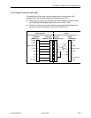
DSX-1 Adapter (Feature No. 9008-F1-560)
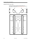
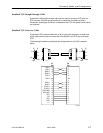
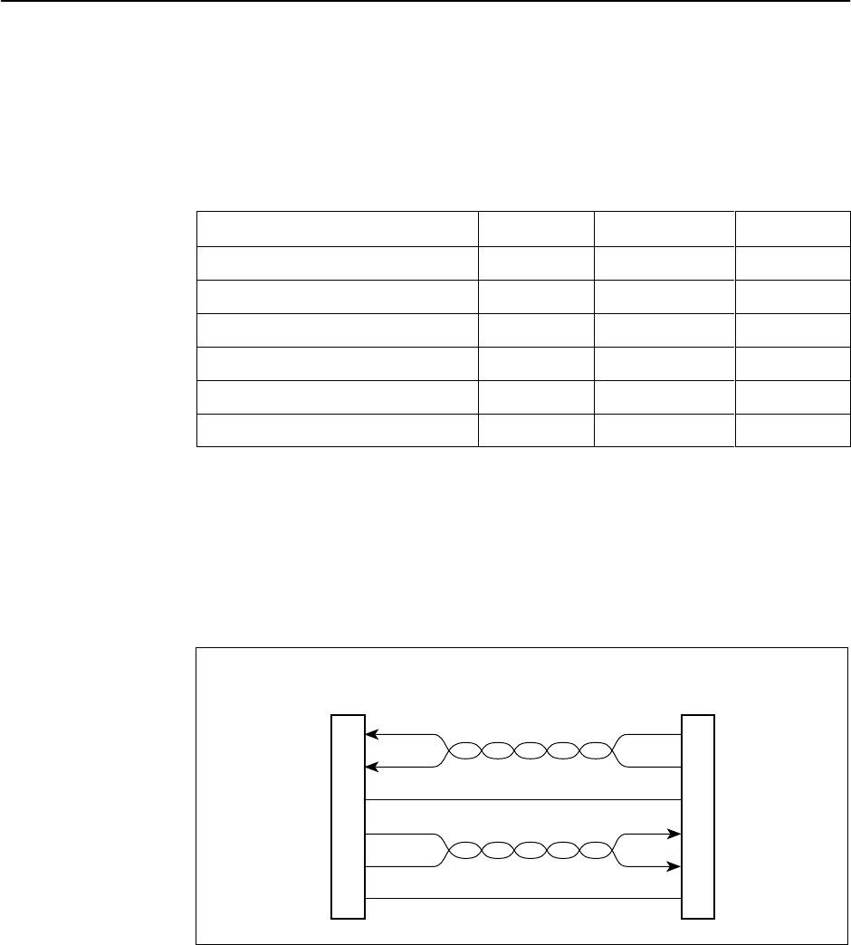
The DSX-1 adapter cable is used as an interface between the unit’s DSX-1
connector and the DTE’s DB15 interface. The following shows pin assignments
and the purpose of each.
99-16216a
9
1
4
11
3
2
Receive Ring
Receive Tip
Shield
Transmit Ring
Transmit Tip
Shield
DB15
Socket
1
2
3
4
5
6
8-Position
Modular Plug
Unkeyed
Blue
White/Blue
Orange
White/Orange
Blue
White/Blue
Orange
White/Orange
Receive Ring
Receive Tip
Shield
Transmit Ring
Transmit Tip
Shield


