Chapter 1. Remote Control sessions overview 51
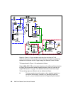
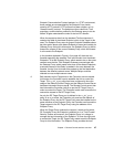
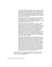
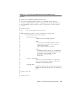
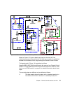
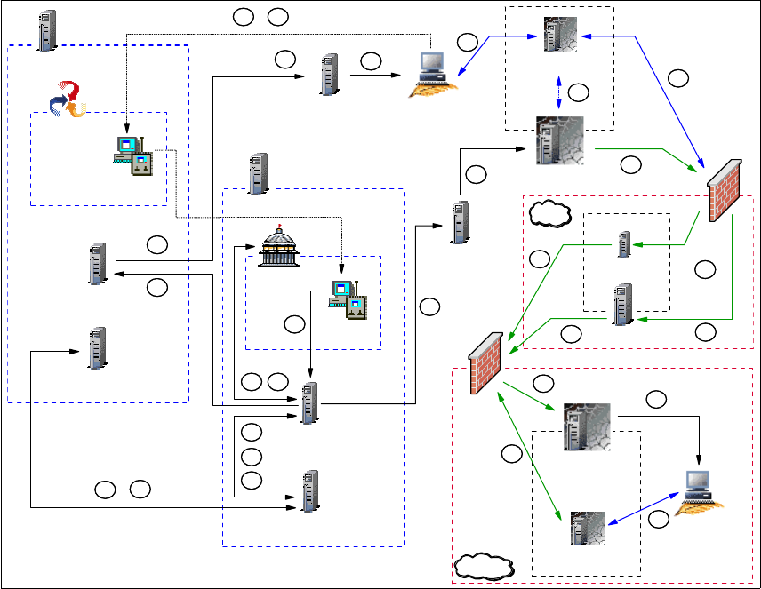
Figure 1-9 RC session data flow in an RC Proxy-TFST/multi-TMR environment
Based on Figure 1-9, here we detail each step from the time the Tivoli
Administrator opens a Remote Control Tool until the connection is established
between the Controller and the Target through the Remote Control Proxies.
The legend used in Figure 1-9 is explained as follows:
Steps A, B,C, D, E, F, G, H, I and K remain the same as for a Remote Control
session in a multi-TMR environment without firewall restriction. Refer to “Data
flow for a multi-TMR session” on page 21 for detailed information about these
steps.
The remaining steps are different and are defined as follows:
J This step remains almost the same as for a standard session in a
non-secure environment. However, in a standard process, the
Spoke RC
Server
Controller
Spoke RC
Tool
Spoke
PR
Spoke TMR Server
Spoke Endpoint Mgr
HUB
Endpoint GW
B
K
Spoke RC
Tool
HUB TMR Server
G
HUB RCL
Collection
HUB RC
Server
C
D
A
E
F
H
I
J
K
K
K
L
HUB Endpoint Mgr
A
L
RC Target Proxy
Endpoint Proxy
Target
J
Firewall
RC Contr. Proxy
Gateway Proxy
L
L
J
L
DMZ
Firewall
Relay 1 TFST
Relay 2 TFST
J
J
J
L
L
Spoke
Endpoint GW
J
External


