


122 IBM Tivoli Remote Control Across Firewalls
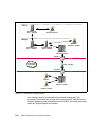
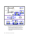
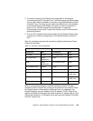
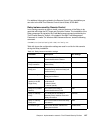
Figure 4-3 Data flow overview: Non-Standalone scenario
To briefly describe how the data flow structure is, we numbered each connection
reported in Figure 4-3 specifying the ports required to establish each connection.
Follow a brief description of each number:
1. The Remote Control Controller connects to the RC Target Proxy using the
proxy port specified in the rc_def_proxy policy method on the Spoke TMR.
This policy method is only applied to the Policy Region in which the Remote
Control Tool has been created. In our case the value of this port is 5020. The
Controller itself uses a random port to establish a connection to port 5020 on
the RC Target Proxy. This random port could also be fixed to a specific port
by modifying the rc_def_ports policy method on the Spoke TMR. For more
information on this matter you can refer to the
IBM Tivoli Remote Control
User’s Guide
, SC23-4842. The RC Target Proxy contacts the Endpoint Proxy
to find out the path to the requested Target.
2. The Endpoint Proxy then provides to the RC Target Proxy the hostname of
the Gateway Proxy responsible for that Target. The RC Target Proxy uses
that information to initiate the connection to the RC Controller Proxy. In our
environment the RC Target Proxy uses a pre-defined range of ports
(4000-4010) to establish a connection to port 7020 defined on the second
instance of the Relay. This range of ports need to be defined
after the
installation of the RC Target Proxy. Information on how to customize it will be
provided in 4.3.2, “Remote Control Proxy configuration” on page 129.
Communications from the RC Target Proxy machine to port 7020 should be
allowed by firewall 1.
Firewall 1
RC Controller Proxy
- child -
Remote Control
Controller
RC Target Proxy
- parent -
- unidirectional -
Target
Endpoint
1Random 5020
Relay
instance 2
Endpoint
Proxy
Gateway
Proxy
2
Range
4000-4010
7020
3
Range
4023-4024
8020
4Random 2501
Firewall 2
1
2