86 IBM Tivoli Remote Control Across Firewalls
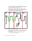
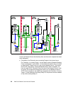
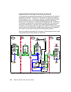
In this scenario, we decided on the more secure solution and decide to
connect the RC Target Proxy B2 to the Relay B2. In addition to that, RC
Controller Proxy B is the Parent and, as a Parent could have more than one
Child, this allows us to connect the Relay B2 and the RC Target Proxy B1 to
the RC Controller Proxy B or to connect the Relay B1 and the RC Target
Proxy B2 to the Relay B2.
As per existing security guidelines, the Security Officer of the CSI Corporation
imposes only a requirement that the components placed in the more secure
site of each firewall are able to initiate the communication to the component
on the less secure side. This means only a unidirectional communication from
the RC Controller Proxy B to the RC Target Proxy B1 and to the RC Target
Proxy B2 is allowed. In this scenario, Controller 1 and Controller 2 are able to
contact Target 2 using the B path.
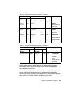
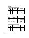
The following tables summarize all needed network communications ports that
may help in configuring both the Remote Control Proxies and TFST components,
as well as the firewalls for Solution A.
Note that the ports provided in the following tables are examples used in this
particular case study scenario only.
Table 2-9 RC Proxy network ports for firewall 1 - Solution A
Source Destination Protocol Description
Type
(Service)
Ports Type
(Service)
Ports
Relay A2
(Relay)
8115 Target Proxy A
(rcproxy)
8116 TCP Firewall rule
needed.
Initiated at service
startup time.
Polling interval is 2
seconds.
Relay B1
(Relay)
9215 Target Proxy B1
(rcproxy)
9216 TCP Firewall rule
needed.
Started at service
time.
Polling interval is 2
seconds.


