


100 IBM Tivoli Remote Control Across Firewalls
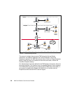
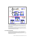
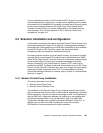
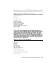
The schema reported in Figure 3-3 shows an overview of the data flow in our
Remote Control StandAlone environment.
Figure 3-3 Remote Control Data Flow Overview
To briefly describe how the data flow structure is, we numbered each connection
reported in Example 3-3, specifying the ports required to establish each
connection. Following is a brief description of each number:
1. The Remote Control Controller connects to the RC Target Proxy using the
proxy port specified in the rc_def_proxy policy method on the Spoke TMR.
This policy method is only applied to the Policy Region in which the Remote
Control Tool has been created. In our case the value of this port is 8888. The
Controller itself uses a random port to establish a connection to port 8888 on
the RC Target Proxy. This random port could also be fixed to a specific port
by modifying the rc_def_ports policy method on the Spoke TMR. For more
information on this matter, you can refer to the
IBM Tivoli Remote Control
User’s Guide
, SC23-4842.
2. Since this is a unidirectional configuration, we defined the RC Target Proxy to
be responsible for initiating the connection to the RC Controller Proxy. In our
environment the RC Target Proxy uses a random port to establish a
connection to port 30008 defined on the RC Controller Proxy. This random
port could also be either a fixed port or use a pre-defined range of ports.
Information on how to customize it is provided in 3.3.2, “Remote Control
Proxy configuration” on page 104. Communications from the RC Target Proxy
machine to port 30008 should be allowed by the firewall.
3. Then the RC Controller Proxy communicates with the Endpoint Target using
a random port, while the Target listens on the default Remote Control port
2501.
Firewall
RC Controller Proxy
- child -
Remote Control
Controller
RC Target Proxy
- parent -
- unidirectional -
Target
Endpoint
1
Random 8888
2
Random
30008
3
Random 2501