


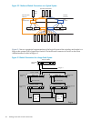
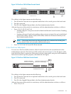
3.3.3.1 Switch Connections and HP Workstations
HP model xw workstations do not have console ports. Only the Root Administration Switch
supports mixing nodes without console management ports with nodes that have console
management ports (that is, all other supported server models).
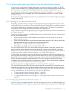
HP workstations connected to the Root Administration Switch must be connected to the next
lower-numbered contiguous set of ports immediately below the nodes that have console
management ports.
For example, if nodes with console management ports are connected to ports 42 through 36 on
the Root Administration Switch, the console ports are connected to ports 42 through 36 on the
Console Switch. Workstations must be connected starting at port 35 and lower to the Root
Administration Switch; the corresponding ports on the Console Switch are empty.
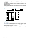
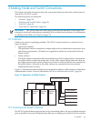
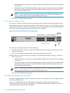
3.3.4 Super Root Switch
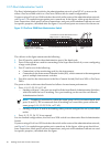
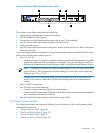
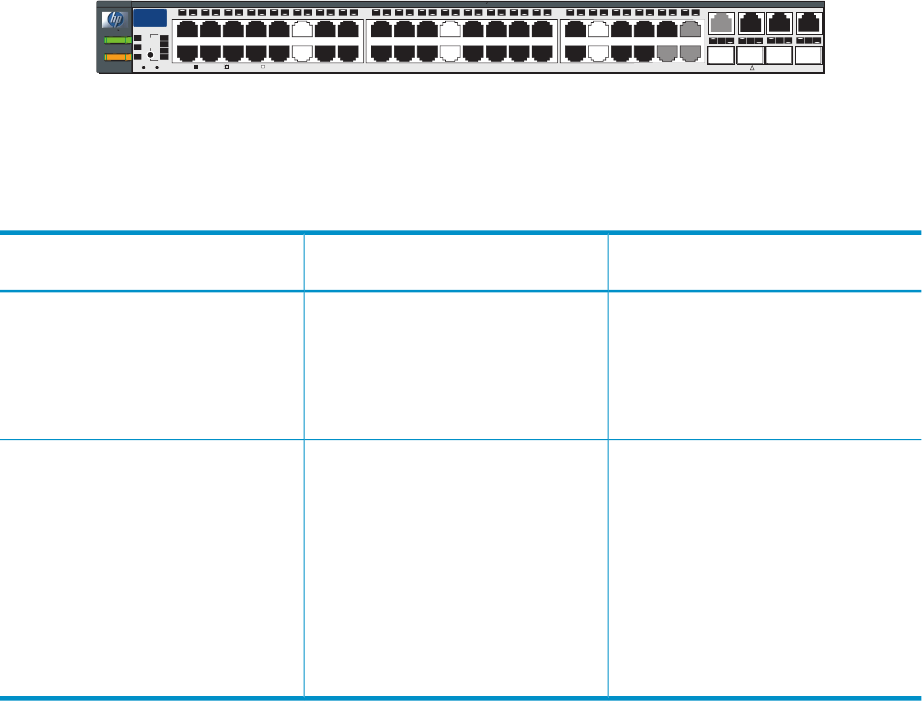
Figure 3-4 shows the Super Root Switch, which is a ProCurve 2848. A Super Root switch
configuration supports the use of trunking to expand the bandwidth of the connection between
the Root Administration Switch and the Super Root Switch. The connection can be as simple as
one wire and as complex as four. See “Trunking and Switch Choices” (page 45) for more
information about trunking and the Super Root Switch.
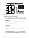
You must configure trunks on both switches before plugging in the cables between the switches.
Otherwise, a loop is created between the two switches.
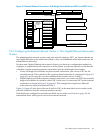
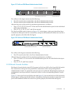
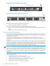
Figure 3-4 illustrates a ProCurve 2848 Super Root Switch.
Figure 3-4 ProCurve 2848 Super Root Switch
LED
Mode
Cl
ear
Re
se t
4
5 43
4442
41
40
39
38
37
36
35
34
33
32
31
30
29
28
27
26
25
24
23
22
21
20
19
18
17
16
15
14
13
12
11
10
9
8
7
6
Spd mode: o ff=10Mbps fla s h=1 0 0Mbps on=10 0 0Mbps
1 15 17
16
18
31
32
33
34
Po w er
Fa
ul t
hp procurve
switch
2848
J4 904 A
Us
eonl yone(TorM)fo rea chG igabit port
!
1
2
3
Spd
Ln k
Ac
t
FD
x
10/100/1000 Base-TX RJ-45 Ports
Ports 1, 3, 5, and 7
are the first four ports
located on the top row
Gigabit
Ethernet Ports
48
47
T
M
T
M
46
45
T
M
T
M
RPS
Fan
Test
Ports 2, 4, 6, and 8
are the first four ports
located on the bottom row
Table 3-2 shows how ports are allocated for large-scale systems with multiple regions.
Table 3-2 Trunking Port Use on Large-Scale Systems with Multiple Regions
Ports Used on Root Administration
SwitchPorts Used on Super Root SwitchTrunking Type
4-wire Trunking:
43 through 461 through 4Region 1
43 through 465 through 8Region 2
43 through 4613 through 16Region 3
2-wire Trunking:
45 and 461 and 2Region 1
45 and 463 and 4Region 2
45 and 465 and 6Region 3
45 and 467 and 8Region 4
45 and 469 and 10Region 5
45 and 4613 and 14Region 6
3.3 Switches 49