


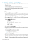
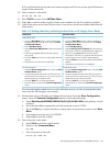


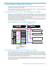

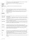
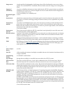
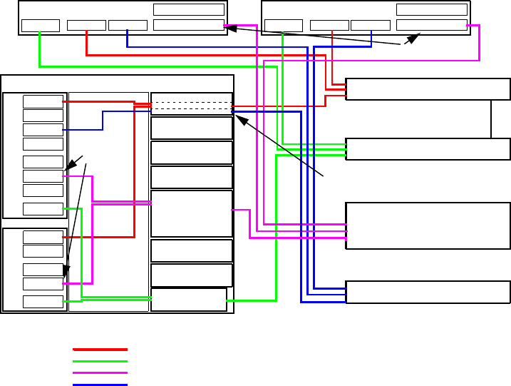
Figure B-2 InfiniBand Interconnect With Full-Height Server Blades
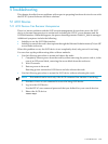
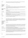
NIC 1
NIC 2
NIC 3
NIC 4
MEZZ 1
MEZZ 2
MEZZ 3
iLO2
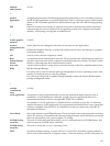
NIC 1
NIC 2
MEZZ 1
MEZZ 2
iLO2
Interconnect bay 1
Interconnect bay 2
Interconnect bay 3
Interconnect bay 4
Interconnect bays
Interconnect bay 7
Interconnect bay 8
ONBOARD
ADMINISTRATOR
MGT
NIC
PCI SLOT
PCI SLOT
NIC
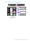
Non-Blade Server
C-Class Blade Enclosure
Admin ProCurve 2800 Series Switch
Console ProCurve 2600 Series Switch
InfiniBand Interconnect Switch
MGT
NIC
PCI SLOT
PCI SLOT
NIC
Non-Blade Server
ADMIN NET VLAN
EXTERNAL NET VLAN
External Public Network
KEY
Administration Network
Console Network
Cluster Interconnect Network
E D A L B T H G I E H L L U F
E D
A
L
B
T
H G I
E
H F
L A H
5 & 6 (double wide)
InfiniBand PCI Cards
InfiniBand
Mezzanine
Cards
Ethernet Switch using VLANs
KEY
Administration Network
Console Network
Cluster Interconnect Network
External Network
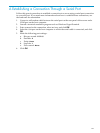
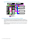
B.3 InfiniBand Interconnect With Mixed Height Server Blades
The configuration shown in Figure B-3 is similar to the configuration shown in Figure B-1
(page 143). The only exception is that in this configuration, the half-height server blades require
external connections as well. Because half-height blades have two NICs, you must use NIC2 for
the connection to the external network. This also means that an interconnect module is required
in bay 2.
On the non-blade server nodes, the built-in NICs are used for the external network connection.
Available ports vary based on hardware model. See Chapter 3 (page 45) for more information
about port assignments.
144 Server Blade Configuration Examples