


Specific HP XC Setup Guidelines
The following enclosure setup guidelines are specific to HP XC:
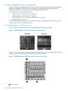
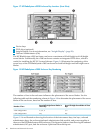
• On every HP BladeSystem c7000 enclosure, an Ethernet interconnect module (either a switch
or pass-through module) is installed in interconnect bay #1 (see callout 2 in Figure 1-4) for
the administration network.
• Hardware configurations that use Gigabit Ethernet as the interconnect require an additional
Ethernet interconnect module (either a switch or pass-through module) to be installed in
interconnect bay #2 (see callout 3 in Figure 1-4) for the interconnect network.
• Systems that use InfiniBand as the interconnect require a double-wide InfiniBand interconnect
switch module installed in interconnect bays #5 and #6 (see callouts 6 and 7 in Figure 1-4).
• Some systems might need an additional Ethernet interconnect module to support server
blades that require external connections. For more information about external connections,
see “Cabling for the External Network” (page 41).
1.2.2 HP BladeSystem c3000 Enclosure
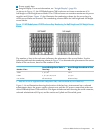
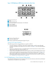
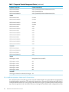
Figure 1-5 shows the front and rear views of the HP BladeSystem c3000 enclosure.
Figure 1-5 HP BladeSystem c3000 Enclosure (Front and Rear Views)
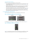
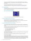
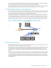
The HP BladeSystem c3000 Enclosure is available as a tower model, as shown in Figure 1-6.
Figure 1-6 HP BladeSystem c3000 Enclosure Tower Model
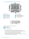
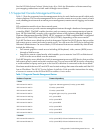
Figure 1-7 is an illustration showing the location of the device bays, optional DVD drive, Insight
display, and Onboard Administrator at the front of the HP BladeSystem c3000 Enclosure.
1.2 Server Blade Enclosure Components 25