


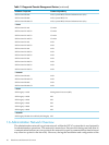
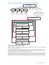
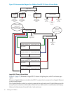
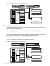
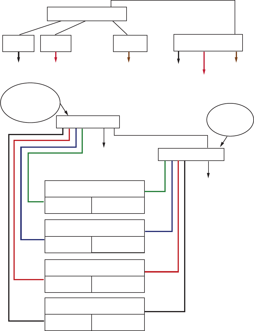
Figure 2-2 Interconnection Diagram for a Medium Sized HP XC Cluster of Server Blades
Enclosure 4
Smaller systems
may use
ProCurve 2626
ProCurve 2650
ProCurve 2848
Enclosure 1
Switch 1
Enclosure 1
Server Blades
NIC1
Enclosure 2
Server Blades
NIC1
Enclosure 3
Server Blades
NIC1
Primary OA Ext LinkSecondary OA Ext Link
GigE Switch
Enclosure 3
Primary OA Ext LinkSecondary OA Ext Link
GigE Switch
Enclosure 2
Primary OA Ext LinkSecondary OA Ext Link
GigE Switch
Enclosure 1
Primary OA Ext LinkSecondary OA Ext Link
GigE Switch
Enclosure 2
Switch 1
Enclosure 32
Switch 1
Enclosure 1
OA
Ext Link
Enclosure 2
OA
Ext Link
Enclosure 32
OA
Ext Link
Enclosure 32
OA
Ext Link
Enclosure 32
GigE switch
May be any
ProCurve managed
GigE switch
(smaller systems may use
ProCurve 2824)
. . .
. . .
ProCurve 2650
GigE Switch
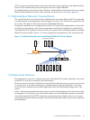
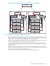
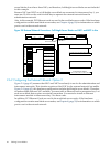
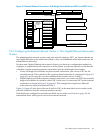
Large HP XC Cluster of Server Blades
Figure 2-3 (page 37) illustrates a large HP XC cluster of eight regions, with 32 enclosures per
region.
There is a Gigabit Ethernet switch for the HP XC system that is connected to a Gigabit Ethernet
switch in each region.
The Gigabit Ethernet switch in a region is connected to each enclosure's Gigabit Ethernet switch
in bay 1 and to a ProCurve 2650 switch. The ProCurve 2650 switch is connected to the Primary
Onboard Administrator External Link of each enclosure.
36 Cabling Server Blades